Schweitzer Engineering Laboratories, Inc. SEL-487E-3, -4 Data Sheet
19
temperature, the thermal element calculates the top-oil
temperature and hot-spot temperature. In the absence of
any measured ambient or top-oil temperatures, the ther-
mal element uses a default ambient temperature setting
that you select and calculates the top-oil and hot-spot tem-
peratures. The relay uses hot-spot temperature as a basis
for calculating the insulation aging acceleration factor
(FAA) and loss-of-life quantities. Use the thermal element
to indicate alarm conditions and/or activate control actions
when one or more of the following exceed settable limits:
➤ Top-oil temperature
➤ Winding hot-spot temperature
➤ Insulation FAA
➤ Daily loss-of-life
➤ Total loss-of-life
Generate a thermal monitor report that indicates the pres-
ent thermal status of the transformer. Historical thermal
event reports and profile data are stored in the relay in
hourly format for the previous 24 hours and in daily for-
mat for the previous 31 days.
Through-Fault Event Monitor
A through fault is an overcurrent event external to the
differential protection zone. Though a through fault is
not an in-zone event, the currents required to feed this
external fault can cause great stress on the apparatus inside
the differential protection zone. Through-fault currents
can cause transformer winding displacement leading to
mechanical damage and increased transformer thermal
wear because of mechanical stress of insulation compo-
nents in the transformer. The SEL-487E through-fault
event monitor gathers current level, duration, and date/
time for each through fault. The monitor also calculates a
I
2
t and cumulatively stores these data per phase. The
SEL-487E through-fault report also provides percent of
total through-fault accumulated according to the IEEE
Guide for Liquid-Immersed Transformer Through-Fault-
Current Duration, IEEE C57.109-1993. Use through-
fault event data to schedule proactive transformer bank
maintenance and help justify through-fault mitigation
efforts. Apply the accumulated I
2
t alarm capability of the
relay to indicate excess through-fault current over time.
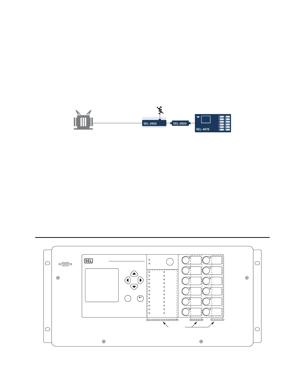
Diagrams and Dimensions
Figure 25 Typical One-Line Diagram for Collecting Transformer Temperature Data
Top-Oil Temperature (RTD)
Ambient
Temperature
RTD
Figure 26 5U Front Panel, Rack-Mount Option
Opening
i7116e
TRIP
BREAKER
T01
ENABLE
DIRECTIONAL
OVER
CURRENT
RESET
BREAKER
WEAR
LEVELS
TRIP
BREAKER
S01
CLOSE
BREAKER
T01
EVENT
SUMMARY
ENABLE
ADAPTIVE
OVER
CURRENT
CLOSE
BREAKER
S01
VAV O N
T BRKR FAIL
REF
S BRKR FAIL
C PH DIFF
LOP V
THRU-FAULT
ALARM
B PH DIFF
TRIP T
A PH DIF F
TRIP S
COMMS
ALARM
HARM BLOCK
DIRECTIONAL
POWER
VCV ON
VBV ON
O/U FREQ
VOLTS/Hz
O/U VOLTAGE
OVER
CURRENT
FREQ OK
EXTERNAL
FAULT
IRIG OK
INSULATION
ALARM
TRIP
ENABLED
TAR GE T
RESET
ENT
ESC
SEL–487E
SCHWEITZER
ENGINEERING
LABORATORIES
PORT F