SEL-487E-3, -4 Data Sheet Schweitzer Engineering Laboratories, Inc.
18
➤
Targets asserted during the fault
➤ Current magnitudes and angles for each terminal
➤ Voltage magnitudes and angles
➤ Differential operate and restraint current
magnitudes
➤ Breaker status (open/close)
With an appropriate setting, the relay sends an event
summary in ASCII text automatically to one or more
serial ports each time an event report is triggered.
SER
Use this feature to gain a broad perspective of relay ele-
ment operation. Items that trigger an SER entry are select-
able and can include as many as 250 monitoring points,
such as I/O change-of-state and element pickup/dropout.
The relay SER stores the latest 1000 events.
Analog Signal Profiling
The relay provides analog signal profiling for as many as
20 analog quantities. Select any analog quantity mea-
sured or calculated by the relay for analog signal profil-
ing. You can select signal sampling rates of 1, 5, 15, 30,
and 60 minutes through settings. The analog signal pro-
file report provides a comma-separated variable (CSV)
list that you can load into any spreadsheet or database for
analysis and graphical display.
SEL
OGIC enable/disable functions can start and stop signal
profiling based on Boolean or analog comparison conditions.
Substation Battery Monitor for DC
Quality Assurance
The relay measures and reports the substation battery
voltage for up to two battery systems. The SEL-411L,
SEL-421, SEL-451 support two battery monitors while
the SEL-487B, SEL-487E, and SEL-487V support one.
Each battery monitor supports programmable threshold
comparators and associated logic provides alarm and
control for batteries and chargers. The relay also pro-
vides dual ground detection. Monitor dc system status
alarms with an SEL communications processor and trig-
ger messages, telephone calls, or other actions.
The measured dc voltage is reported in the
METER display
via serial port communications, on the LCD, and in the
event report. Use the event report data to see an oscillo-
graphic display of the battery voltage. Monitor the sub-
station battery voltage drops during trip, close, and other
control operations.
Breaker Contact Wear Monitoring
Circuit breakers experience mechanical and electrical wear
during each operation. Effective scheduling of breaker
maintenance takes into account the manufacturer’s pub-
lished data of contact wear versus interruption levels and
operation count.
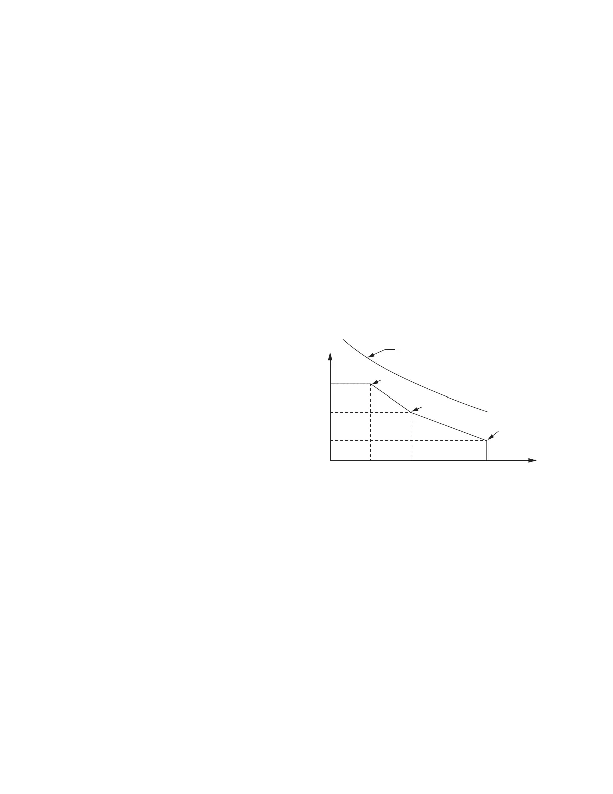
➤ Every time the breaker trips, the relay integrates
interrupted current. When the result of this integration
exceeds the threshold set by the breaker wear curve
(Figure 24), the relay can alarm via an output contact
or the optional front-panel display. With this
information, you can schedule breaker maintenance
in a timely, economical fashion.
➤ The relay monitors last and average mechanical and
electrical interruption time per pole. You can easily
determine if operating time is increasing beyond
reasonable tolerance and then schedule proactive
breaker maintenance. You can activate an alarm
point if operation time exceeds a preset value.
The relay also monitors breaker motor run time, pole dis-
crepancy, and breaker inactivity.
Transformer Thermal Monitoring
Transformer thermal monitoring for mineral-oil immersed
transformers is a standard feature in the SEL-487E. Spec-
ify the SEL-487E to provide this capability for monitor-
ing and protection of a single three-phase transformer, as
well as for monitoring and protection of three independent
single-phase units. Use the thermal element to activate a
control action or issue a warning or alarm when your trans-
former overheats or is in danger of excessive insulation
aging or loss of life.
The thermal element operates in one of three modes, depend-
ing upon the presence or lack of measured temperature
inputs: 1) measured ambient and top-oil temperature inputs,
2) measured ambient temperature only, and 3) no mea-
sured temperature inputs. If the relay receives measured
ambient and top-oil temperatures, the thermal element
calculates hot-spot temperature. When the relay receives
a measurement of ambient temperature without top-oil
Figure 24 Breaker Contact Wear Curve and Settings
kA Interrupted
(Set Point 1)
(Set Point 2)
(Set Point 3)
Breaker Manufacturer's
Maintenance Curve
Close to Open Operations