26
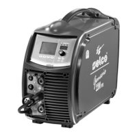
4.4 RC 180 remote control
This remote control unit makes it possible to change the output
current without interrupting the welding process.
“Consult the instruction manual”.
5 MAINTENANCE
Routine maintenance must be carried out on the
system according to the manufacturer’s instruc-
tions.
Any maintenance operation must be performed by qualified
personnel only.
When the equipment is working, all the access and operating
doors and covers must be closed and locked.
Unauthorized changes to the system are strictly forbidden.
Prevent conductive dust from accumulating near the louvers
and over them.
Disconnect the power supply before every opera-
tion!
Carry out the following periodic checks on the
power source:
- Clean the power source inside by means of
low-pressure compressed air and soft bristle
brushes.
- Check the electric connections and all the con-
nection cables.
For the maintenance or replacement of torch components,
electrode holders and/or earth cables:
Check the temperature of the component and
make sure that they are not overheated.
Always use gloves in compliance with the safety
standards.
Use suitable wrenches and tools.
Failure to carry out the above maintenance will invalidate all
warranties and exempt the manufacturer from any liability.
6 TROUBLESHOOTING
The repair or replacement of any parts in the
system must be carried out only by qualified
personnel.
The repair or replacement of any parts in the system by unau-
thorised personnel will invalidate the product warranty.
The system must not be modified in any way.
The manufacturer disclaims any responsibility if the user
fails to follow these instructions.
The system fails to come on (green LED off)
Cause No mains voltage at the socket.
Solution Check and repair the electrical system as needed.
Use qualified personnel only.
Cause Faulty plug or cable.
Solution Replace the faulty component.
Contact the nearest service centre to have the sys-
tem repaired.
Cause Line fuse blown.
Solution Replace the faulty component.
Cause Faulty on/off switch.
Solution Replace the faulty component.
Contact the nearest service centre to have the sys-
tem repaired.
Cause Faulty electronics.
Solution Contact the nearest service centre to have the sys-
tem repaired.
No output power (the system does not weld)
Cause The system has overheated (temperature alarm -
yellow LED on).
Solution Wait for the system to cool down without switching
it off.
Cause Incorrect earth connection.
Solution Earth the system correctly.
Read the paragraph “Installation “.
Cause Faulty electronics.
Solution Contact the nearest service centre to have the sys-
tem repaired.
Incorrect output power
Cause Incorrect selection in the welding process or faulty
selector switch.
Solution Select the welding process correctly.
Replace the faulty component.
Contact the nearest service centre to have the sys-
tem repaired.
Cause System parameters or functions set incorrectly.
Solution Reset the system and the welding parameters.
Cause Faulty potentiometer/encoder for the adjustment
of the welding current.
Solution Replace the faulty component.
Contact the nearest service centre to have the sys-
tem repaired.