In the set-up menu a different parameter list is displayed in relation to the selected welding procedure. Some fixed positions identify
common parameters or special functions and are described below.
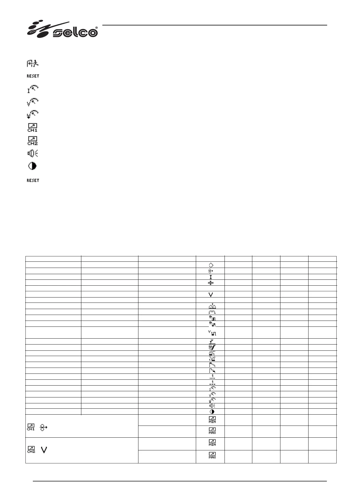
Set-up no. 0: quit and return to the main menu, with storage of the modifications.
Set-up no. 1: reset. The Selco default settings are restored.
Set-up no. 40: reading of welding current (read-only parameter, non-modifiable).
Set-up no. 41: reading of welding voltage (read-only parameter, non-modifiable).
Set-up no. 42: reading of measurement of gas flow in l/min (read-only parameter, non-modifiable).
Set-up no. 45: channel 1 remote control minimum and maximum value setting menu.
Set-up no. 46: channel 2 remote control minimum and maximum value setting menu.
Set-up no. 48: buzzer tone adjustment.
Set-up no. 49: display D1 contrast adjustment.
Set-up no. 99: general reset of all menus and settings performed. The Selco default settings and menus are restored.
In the set-up parameters list there are fictitious parameters such as the current, voltage and gas flow measurements: these "parameters"
behave exactly like all the others (and can therefore appear in the menus, be chosen as main parameters, etc. …), but obviously can-
not be modified with the encoder E1. These measurements are usually shown in the 7-segment display D2.
1.3.7 WF 110 default settings
The default settings for the main menu, quick menu and set-up of the related parameters are listed below for each procedure. The
synergic parameters are highlighted in bold.
MIG SHORT SYNERGIC (procedure set by default)
MAIN MENU
Wire speed
Synergy voltage
Offset voltage
SET-UP MENU CH1 RC07
SET-UP MENU CH2 RC07
QUICK MENU
Program number
Wire speed
Current
Thickness
Synergy voltage
Offset voltage
Minimum current
Minimum current offset
Inductance
Double pulsed amplitude
Double pulsed time **
Doubled pulsed voltage
delta **
Initial increase **
Crater Filler **
Spot welding time **
Pause time **
SET-UP MENU
2-Program number
3-Wire speed
4-Current
5-Thickness
6-Synergy voltage
6-Offset voltage
7-Minimum current
7-Minimum current offset
8-Inductance
9-Double pulsed amplitude
10-Double pulsed time
11-Doubled pulsed volta-
ge delta
12-Burn back
13-Softstart
14-Pre-gas time
15-Post-gas time
16-Initial increase
17-Crater Filler
18-Spot welding time
19-Pause time
40-Current reading
41-Voltage reading
42-Gas flow reading
48-Buzzer tone
49-LCD contrast
45-CH1: min wire speed
RC07
45-CH1: max wire speed
RC07
46-CH2: min voltage off-
set RC07
46-CH2: max voltage off-
set RC07
26
SYMBOL
#
#
MIN
Off (0)
1,0 *
6 *
0,8 *
5,0 *
-9,9 *
12 *
-50 *
12
0
0,0
-5,0
0,01
10
0,0
0,0
20
20
0,1
0,1
-
-
-
Off (0)
0
1,0
min+1
-9,9
min+ 0,1
MAX
60
22,0 *
Imax ***
25,5 *
55,5 *
+9,9 *
250 *
+50 *
100
100
10,0
+5,0
1,00
100
10,0
10,0
200
200
25,0
25,0
-
-
-
10
50
max-1
22,0
max-0,1
+9,9
DEF
5
3,0
-
-
-
0,0
24
0
45
0
0,5
0,0
0,08
50
0,0
2,0
120
80
1,0
1,0
-
-
-
5
25
1,0
22,0
-9,9
+9,9
UM
-
mt/min
A
mm
V
V
A
A
%
%
sec
V
s
%
s
S
%
%
s
s
A
V
lt/min
-
-
mt/min
mt/min
V
V