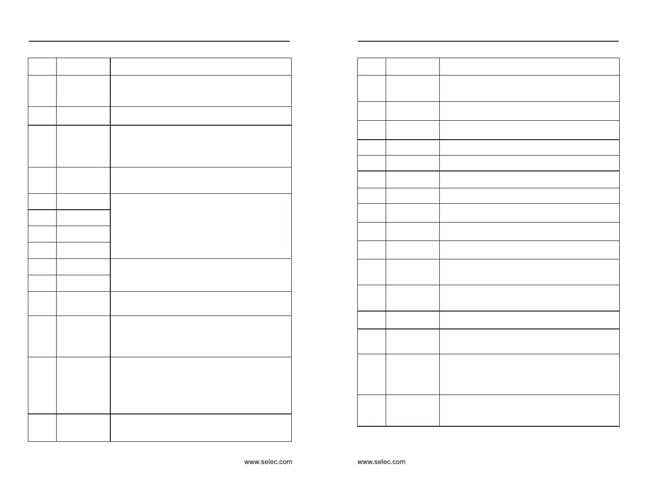
Setting
value
Function Instruction
19
UP and DOWN
setting clear
(terminal,
keyboard)
If the frequency source is digital setting, the terminal is
used to clear the modification by using the UP/DOWN
function or the increment/decrement key on the
operating panel, returning the set frequency to the
value of P0-08.
20
Command
source
switchover
terminal
21
Acceleration &
deceleration
prohibited
Ensure that the inverter is not affected by external
signals (except for shutdown commands), Maintain the
current output frequency.
22
PID pause
The PID temporarily fails, the inverter maintains the
current output frequency, and no PID adjustment is
performed.
23
PLC status
reset
When the PLC runs paused, this terminal can be
restored to the initial state of the PLC.
24
Swing frequency
pause
The frequency converter outputs at the center frequency.
The swing frequency function is suspended.
25
Counter input Count the input terminals of the pulse.
26
Counter reset
The counter status is cleared.
27
Length count
input
Input terminal for length counting.
28
Length reset Zero length
29
Torque control
prohibited
The inverter is prohibited from performing torque control,
and the inverter enters the speed control mode.
30
Pulse frequency
input
X6 functions as a PULSE input terminal
(only X6 is active).
32
Immediate DC
braking
When the terminal is valid, the inverter directly switches
to the DC braking state.
33
Normally closed
(NC) input of
external fault
When the external fault normally closed signal is sent,
the inverter reports ERR15 fault and stops.
34
Frequency
modification
forbidden
If this terminal is valid, frequency modification is
allowed; if The terminal status is invalid, and frequency
modification is prohibited.
35
Reverse PID
action direction
When the terminal is valid, the direction of the PID
action is opposite to the direction set by PA-03.
36
External STOP
terminal 1
When the keyboard is controlled, the terminal can be
stopped, which is equivalent to the STOP button
function on the keyboard.
37
Command
source
switchover
terminal 2
Used for switching between terminal control and
communication control. If the command source is
selected as the terminal control, the system switches to
communication control when the terminal is valid;
vice versa.
38
PID integral
pause
When the terminal is valid, the integral adjustment
function of the PID is suspended, but the proportional
adjustment and differential adjustment functions of the
PID are still valid.
User Manual
90
User Manual
91
If the command source is set to terminal control
(P0-02= 1), this terminal is used to perform switchover
between terminal control and operating panel control.
If the command source is set to communication control
(P0-02 = 2), this terminal is used to perform switchover
between communication control and operating panel
control.
Setting
value
Function Instruction
8
Coast to stop
The inverter blocks the output, and the motor's
stopping process is not controlled by the inverter.
This mode has the same meaning as Coast to stop
described in P6-10.
9
Fault reset
(RESET)
The fault is reset via the terminal. Same as the
RESET button on the keyboard.
10
Run pause
Inverter decelerates to stop, but all operating
parameters are memorized. Such as PLC parameters,
swing frequency parameters, PID parameters. After the
terminal signal disappears, the inverter returns to the
operating state before stopping.
11
Normally open
(NO) input of
external fault
When the signal is activated, the fault ERR15 is
reported and the fault is processed according to the
setting of P9-47.
12
Multi-speed
terminal 1
The 16-segment speed or 16 other commands can
be set by combining the 16 states of the four
terminals. See Table 1 for details.
13
14
15
16
Acc./dec. time
selection 1
Through the combination of the four states of the two
terminals, four kinds of acceleration/deceleration time
are selected. For details, see Appendix 2.
17
Multi-speed
terminal 2
Multi-speed
terminal 3
Multi-speed
terminal 4
Acc./dec. time
selection 2
18
Frequency
source
switchover
This terminal is used to switch the main frequency
between the two frequency sources. See P0-07 for
details.
Chapter 6 Chapter 6

 Loading...