User Manual
Chapter 7
160
User Manual
161
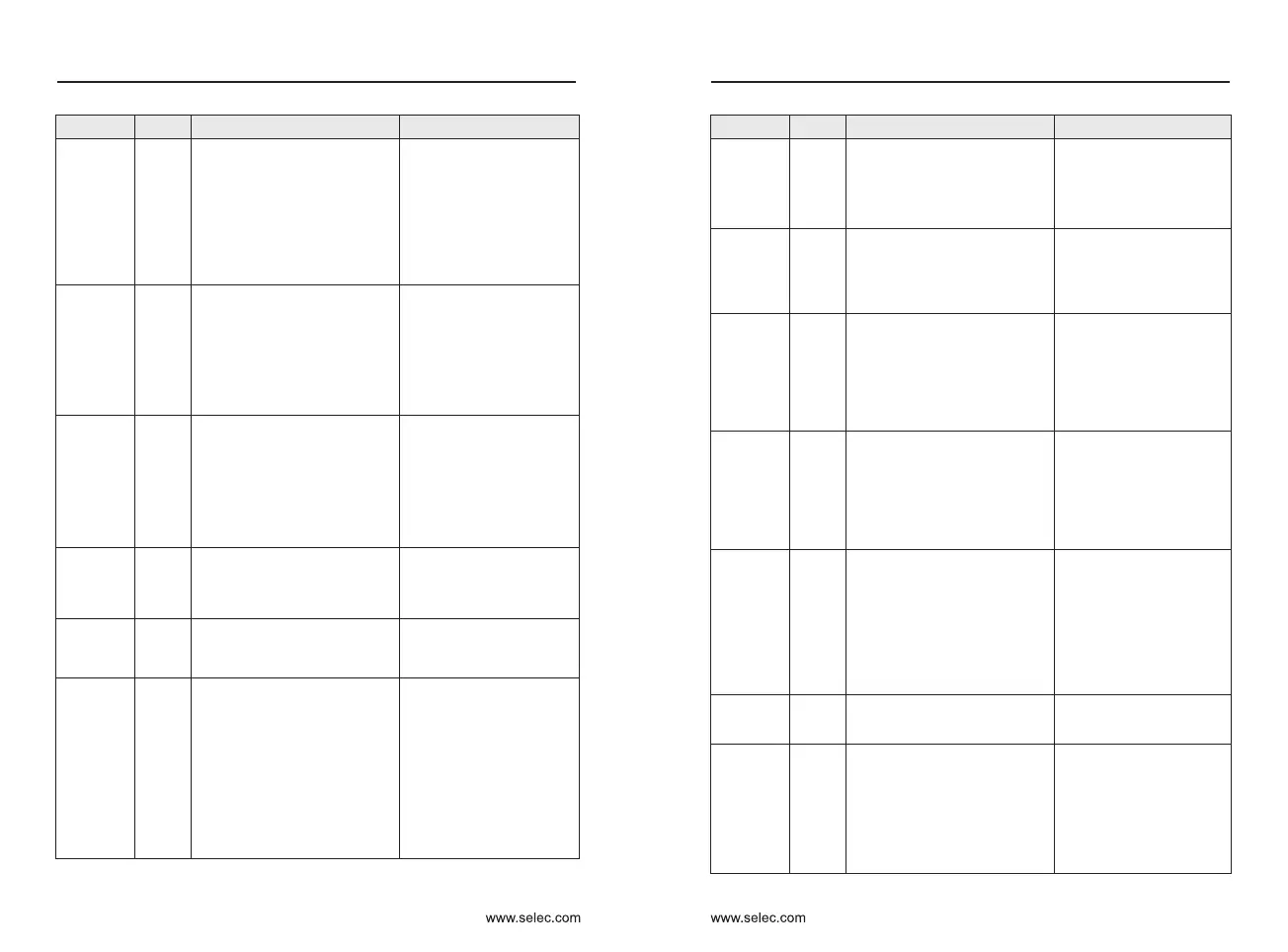
Fault name
Display
Troubleshoot the cause
Solutions
Over-
current at
constant
speed
Err04
Over-
voltage
during
acce-
leration
Err05
Over-
voltage
during
dece-
leration
Err06
Over-
voltage at
onstant
speed
Err07
Control
power
supply fault
Err08
The input voltage is not within
the allowable range.
Adjust the input voltage to
the allowable range.
Under
voltage
Err09
Inverter
overload
Err10
Motor
overload
Err11
Power
input
phase
loss
Err12
Power
output
phase
loss
Err13
IGBT
overheat
Err14
External
equipment
fault
Err15
1: External fault signal is input
via terminal.
Reset the operation.
Commu-
nication
fault
Err16
1: The output circuit is grounded
or short circuited.
2: Motor auto-tuning is not
performed.
3: The voltage is too low.
4: A sudden load is added during
operation.
5: The inverter model is of too
small power class.
1: Eliminate external faults.
2: Perform the motor auto-
tuning.
3: Adjust the voltage to
normal range.
4: Remove the added load.
5: Select an inverter of
higher power class.
1: The input voltage is too high.
2: An external force drives the
motor durifng acceleration.
3: The acceleration time is too
short.
4: The braking unit and braking
resistor are not installed.
1: Adjust the voltage to
normal range.
2: Cancel the external force
or install a braking resistor.
3: Increase the acceleration
time.
4: Install the braking unit
and braking resistor.
1: The input voltage is too high.
2: An external force drives the
motor during deceleration.
3: The deceleration time is too
short.
4: The braking unit and braking
resistor are not installed.
1: Adjust the voltage to
normal range.
2: Cancel the external force
or install the braking resistor.
3: Increase the deceleration
time.
4: Install the braking unit
and braking resistor.
1: The input voltage is too high.
2: An external force drives the
motor during deceleration.
1: Adjust the voltage to
normal range.
2: Cancel the external force
or install the braking resistor.
1: Instantaneous power failure
occurs on the input power
supply.
2: The AC drive's input voltage
is not within the allowable range.
3: The bus voltage is abnormal.
4: The rectifier bridge and buffer
resistor are faulty.
5: The driver board is faulty.
6: The main control board is
faulty.
1: Reset the fault.
2: Adjust the voltage to
normal range.
3: Contact the agent or
company to support.
Fault name
Display
Troubleshoot the cause
Solutions
1: The load is too heavy or
locked rotor occurs on the motor.
2: The inverter model is of too
small power class.
1. Reduce the load and
check the motor and
mechanical conditions.
2, select the inverter with a
larger power level
1: P9-01 is set improperly.
2: The load is too heavy or
locked rotor occurs on the motor.
3: The inverter model is of too
small power class.
1: The three-phase power input
is abnormal.
2: The driver board is faulty.
3: The Lightning protection
board is faulty.
4: The main control board is
faulty.
1: Reduce the load and
check the motor and
mechanical condition.
2: Select an inverter of
higher power class.
1: Eliminate external faults.
2: Contact the agent or
company to support.
1: The cable connecting the
inverter and the motor is faulty.
2: The AC drive's three-phase
outputs are unbalanced when
the motor is running.
3: The driver board is faulty.
4: The IGBT is faulty.
1: Eliminate external faults.
2: Check whether the
motor three-phase winding
is normal.
3: Contact the agent or
company to support.
1: The ambient temperature is
too high.
2: The air filter is blocked.
3: The fan is damaged.
4: The thermally sensitive
resistor of the IGBT is damaged.
5: The inverter IGBT is
damaged.
1: Lower the ambient
temperature.
2: Clean the air filter.
3: Replace the damaged
fan.
4: Replace the damaged
thermally sensitive resistor.
5: Replace the inverter
IGBT.
1: The host controller is in
abnormal state.
2: The communication cable is
faulty.
3: P0-28 is set improperly.
4: The communication
parameters in group PD are set
improperly.
1: Check the cabling of
host controller.
2: Check the commu-
nication cabling.
3: Set P0-28 correctly.
4: Set the communication
parameters properly.
Chapter 7

 Loading...