14
———————— WARNING —————————
Do not use the Adjustable In-Circuit Test Probe
(AP291) to perform the Leakage test. Always use the
Test Leads (39G219) when performing the Leakage
test.
———————— ATTENTION ————————
Ne pas utiliser la sonde adjustable pour les test en
circuit pendant le test de fuite. Toujours utiliser la
sonde (39G219) pour les tests de fuite.
To use the In-Circuit Test Probe:
1. Remove power from the circuit.
2. Connect the In-Circuit Test Probe (AP291) to the
LC103.
3. Zero the test probe.
4. Select a COMPONENT TYPE.
5. Connect the probe tips to the leads of the component
under test.
6. Press and hold the In-Circuit Test Probe’s test
activation button. When the LC103 has finished the
first complete update, three short beeps will sound.
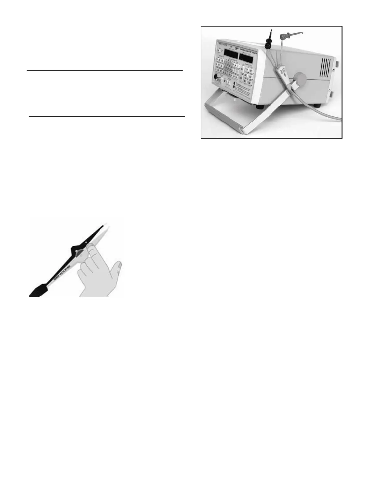
Fig. 8: The test activation button molded into the In-
Circuit Test Probe allows easy in-circuit testing
without taking your eyes off the circuit.
Test Lead Mounting Clip
A TEST LEAD MOUNTING CLIP (64G37) is supplied
with the LC103. This clip is useful to hold the test leads
out of the way when not in use, but keeps them ready
and within reach at any time. The mounting clip may be
attached on the top of the LC103, on the side of the
handle, or wherever it is most convenient. To mount the
clip, peel off the backing, place the clip in the desired
location and press it firmly in place.
Fig. 9: The test lead mounting clip holds the test
leads out of the way, yet ready for use at anytime.
NOTE: Mounting the TEST LEAD MOUNTING CLIP to
the sides of the ReZolver will interfere with the handle
movement.
Lead and Probe Zeroing
The Adjustable In-Circuit Test Probe and Out-of-Circuit
Test Leads used with the LC103 have a small amount of
capacitance, resistance, and inductance. These must be
balanced out before measuring small value capacitors
and inductors or before measuring capacitor ESR. The
test lead impedance should be zeroed when the LC103 is
first turned on. It remains zeroed as long as the unit is
powered on. If the LC103 is battery operated and is
turned off by the auto-off circuits, however, the leads
must be re-zeroed. You will need to re-zero the leads
when switching from the in-circuit to out-of circuit leads
and vice-versa.
To zero the test leads:
1. Turn the LC103 on by pressing the POWER button.
2. Connect the In-Circuit Test Probes or Out-of-Circuit
Test Leads to the TEST LEAD INPUT jack on the
front of the ReZolver.
3. Open the In-Circuit Test Probe or place the Out-of-
Circuit Test Leads on the work area with the red and
black test clips next to each other, but not touching.
4. Press the LEAD ZERO “OPEN” button.
5. The LC103 will display “Lead Zero Open In
Progress” and “Done” when finished.
6. Close the In-Circuit Test Probe or connect the red
and black test clips together.
7. Press the LEAD ZERO “SHORT” button.
8. The LC103 will display “Lead Zero Short In
Progress” and “Done” when finished.