41
INDUCTOR TESTING
The In-Circuit Inductor Test
The LC103 ReZolver can be used to measure the
inductance of a coil with the component still in circuit.
The actual measurement test is very similar to the out-
of-circuit test except for an additional parallel
component check. This check is done automatically
when the in-circuit test is activated. If this test fails the
LC103 will return a measured value along with a
“SUGGEST REMOVAL” message. If the parallel
component check passes, the ReZolver will measure the
true inductance of the coil by measuring the counter
EMF produced as a changing current is applied.
Mutual Inductance
Mutual inductance occurs when two or more coils are
wound on the same form and connected together. In such
cases, the total inductance measured across the windings
will not equal the sum of the measured inductances of
the individual coils. This is due to the mutual inductance
of the coils. The total measured value may be higher or
lower than the individual inductances, depending on
whether the coils are aiding or opposing. In addition, the
effects of mutual inductance depend on the type of core
material, the spacing of the turns, and the type of turns
used. The amount of inductance measured by the
ReZolver will be the same inductance seen by the
circuit.
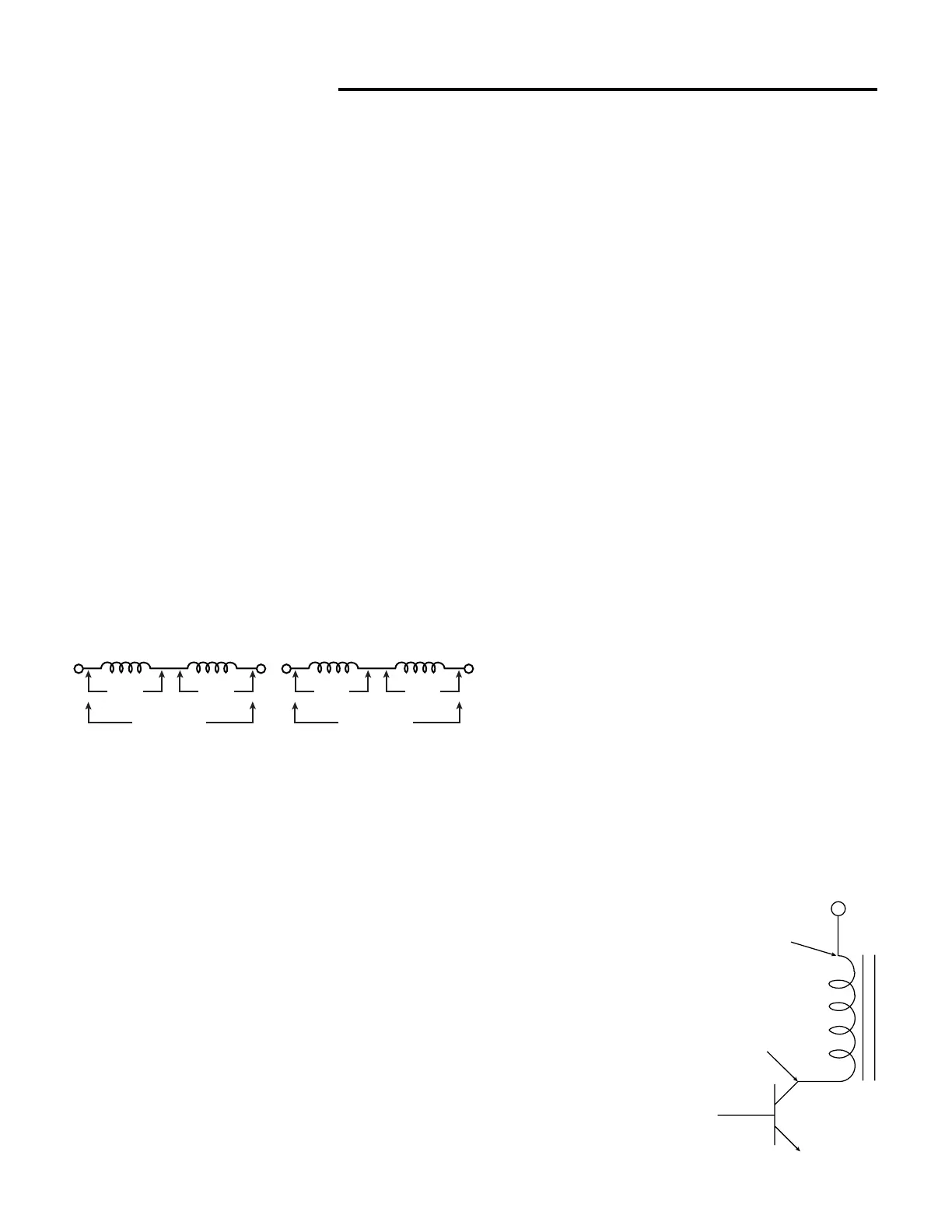
Fig. 30: The effects of mutual inductance may add
or subtract from the sum of the individual
Ringing Peaking Coils
Peaking coils are often wound around a resistor. The
resistor serves to lower the Q of the coil to prevent
ringing. For this reason, some good peaking coils will
not read “good” on the INDUCTOR RINGER test. The
lower the resistor value, the fewer rings the coil will
read.
The best test for peaking coils is to observe the number
of rings, rather than the GOOD/BAD indication, and
compare the coil to an identical known good component.
Ringing Metal Shielded Coils
Sometimes coils, such as IF transformers, may be placed
inside a shield to reduce in-circuit interference. These
shielded coils may not ring “good” when tested with the
INDUCTOR RINGER test because the metal shield
absorbs some of the ring energy. A shielded coil is good
if it rings ten or more. However, if it rings less than ten,
remove the metal shield, if possible, and test the coil
again. If it now rings 10 or more, the coil is good. If you
are unable to remove the metal shield, make a
comparison test using an identical, known good
component.
Testing Flyback Transformers and Deflection Yokes
A flyback transformer is a special type of transformer
which produces the focus and second anode voltages for
a CRT. Many flybacks also have several lower voltage,
relatively high current windings which power other
circuits and the CRT filament. Because of the high
voltages present, a flyback transformer may develop an
internal shorted turn or leakage between windings. A
shorted turn reduces the efficiency of the transformer
and usually causes severe circuit problems. Inductance
measurements are of little value when troubleshooting a
flyback, since a shorted turn causes little change in
inductance value. In addition, the inductance value is
seldom known. The LC103 INDUCTOR RINGER test
will detect a shorted turn in any of the primary or
secondary windings of a flyback. Using the LC103’s
leakage supply, you can find any leakage between
windings.
Ringing Flyback Transformers
A flyback transformer may be tested in or out of circuit
with the LC103 Ringer test, although several external
loads may need to be disconnected before a good
flyback will produce more than 10 rings. Connect the
LC103 to the primary of the flyback and select the
“YOKES & FLYBACKS” COMPONENT TYPE
switch. Press and hold the Inductor Ringer test button
and read the condition of the flyback as “GOOD” or
“BAD” in the LC103 display. If the flyback rings
“BAD”, disconnect any loads until the display reads
“GOOD.” If the flyback is completely disconnected and
still rings “BAD” the flyback has a shorted turn, or the
winding to which the test leads
are connected is open. In either
case, the flyback should be
considered bad.
NOTE: Certain flybacks
have removable cores. The
ferrite core must be installed
inside the windings in order
for the flyback to ring
“GOOD.”
Fig. 31: Connect to the primary
side of a flyback to do the
ringing test.
•• ••
1000 uH 1000 uH
2280 uH
1000 uH 1000 uH
1870 uH
(When Mutual Inductance Adds) (When Mutual Inductance Subtracts)
B+
Black Lead
Red