25
IN-CIRCUIT INDUCTOR TESTING
The LC103 provides an in-circuit inductor value test for
inductor values from 3.18 uH to 3.18 H. When this test
is performed, the LC103 also checks for parallel
components that may upset the measurement. If there are
no parallel components that will upset the measurement,
the ReZolver will return an inductance value reading. If
the LC103 determines that parallel components will alter
the reading it will display SUGGEST REMOVAL along
with the measured value.
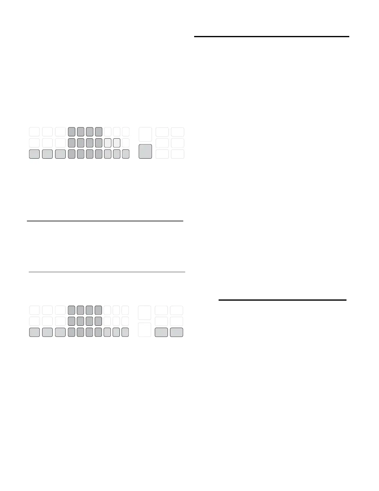
Fig. 14: Controls used for in-circuit inductor testing.
———————— WARNING —————————
Always remove AC power from the circuit when
performing any of the LC103’s In-Circuit test
functions. Failure to do so may result in a shock
hazard and damage to the test instrument.
———————— ATTENTION ————————
Toujours retirer la prise secteur lorsque vous faites
des tests dans le circuit. Si cela n’est pas realize,
l’utilisateur peut recevoir des chocs électriques et
l’équipement peut être endommagé.
To value test an inductor in-circuit:
1. Connect the in-circuit test probe.
2. Zero the test probe.
3. Adjust the width of the probe tips to the inductor
under test.
4. Touch the tips of the probe to the leads of the
inductor.
5. Press and hold the IN-CIRCUIT INDUCTOR TEST
button and read the results in the COMPONENT
TEST RESULTS display.
The LC103 can also perform an automatic GOOD/BAD
in-circuit inductor value test. By selecting an inductor
COMPONENT TYPE and entering the value and
tolerance, the ReZolver will return a GOOD or BAD
message along with the value measurement.
To perform the automatic GOOD/BAD in-circuit
inductor value test:
1. Connect the in-circuit test probe.
2. Zero the test probe.
3. Select an inductor component type.
4. Enter the rated value and tolerance of the inductor.
5. Connect to the inductor under test.
6. Press and hold the TEST ACTIVATION button on
the probe or the IN-CIRCUIT INDUCTOR TEST
button on the front panel.
OUT-OF-CIRCUIT INDUCTOR TESTING
Fig. 15: Controls used for out-of-circuit inductor
testing.
The LC103 ReZolver measures the true inductance of
coils using a fast, reliable patented test. Coils from 0.l
uH to 19.99 H are automatically measured for value by
connecting the test leads and pressing the test button. A
patented Ringer test dynamically checks the “Q” of the
coil and provides a proven GOOD/BAD check.
Measuring Inductor Value
Inductors are tested out-of-circuit for value with the
LC103 by simply connecting the inductor to the test
leads and pushing the INDUCTOR VALUE button. No
component type switches need to be selected to measure
inductan
ce value. Make sure none of the beige capacitor type
buttons are selected, or the LC103 will only display
“Component Type Selection Error” when the inductor
test button is pressed.
To measure inductance value out-of-circuit:
1. Connect the out-of-circuit test leads.
2. Zero the test leads.
3. Connect the inductor to the test leads.
4. Push the INDUCTOR VALUE button.
5. Read the inductance value on the COMPONENT
TEST RESULTS display.
NOTE: The LC103’s display will read “OPEN” if the
component connected to the test leads has more than 8
kohms of resistance when the INDUCTOR VALUE
button is pressed. Check the connections to the inductor.
If you are testing a multi-tap coil or transformer, be sure
you are connected to the proper taps. If the connections
are good, the inductor has an open winding and is bad.
COMPONENT TYPE
NUMERIC INPUT ENTER IN-CIRCUIT OUT-OF-CIRCUIT
COMPONENT PARAMETERS COMPONENT TESTS
ALUMINUM
LYTICS
DOUBLE
LAYER
LYTICS
HIGH R
DOUBLE
LAYER
1234pF µF F
CAPACITOR
GOOD/BAD
INDUCTOR
GOOD/BAD
CAPACITOR
VALUE
CAPACITOR
ESR
CAPACITOR
LEAKAGE
INDUCTOR
RINGER
DIELECTRIC
ABSORPTION
INDUCTOR
VALUE
+ % - % V
µH mH H
5678
90 •CLR
ALL
OTHER
CAPS
SWITCHING
TRANS-
FORMERS
TANTALUM
CAPS
CERAMIC
CAPS
YOKES &
FLYBACKS
COILS
COMPONENT TYPE
NUMERIC INPUT ENTER IN-CIRCUIT OUT-OF-CIRCUIT
COMPONENT PARAMETERS COMPONENT TESTS
ALUMINUM
LYTICS
DOUBLE
LAYER
LY TI C S
HIGH R
DOUBLE
LAYER
1234pF µF F
CAPACITOR
GOOD/BAD
INDUCTOR
GOOD/BAD
CAPACITOR
VALUE
CAPACITOR
ESR
CAPACITOR
LEAKAGE
INDUCTOR
RINGER
DIELECTRIC
ABSORPTION
INDUCTOR
VALUE
+ % - % V
µH mH H
5678
9 0 • CLR
ALL
OTHER
CAPS
SWITCHING
TRANS-
FORMERS
TANTALUM
CAPS
CERAMIC
CAPS
YOKES &
FLYBACKS
COILS