15
ENTERING COMPONENT DATA
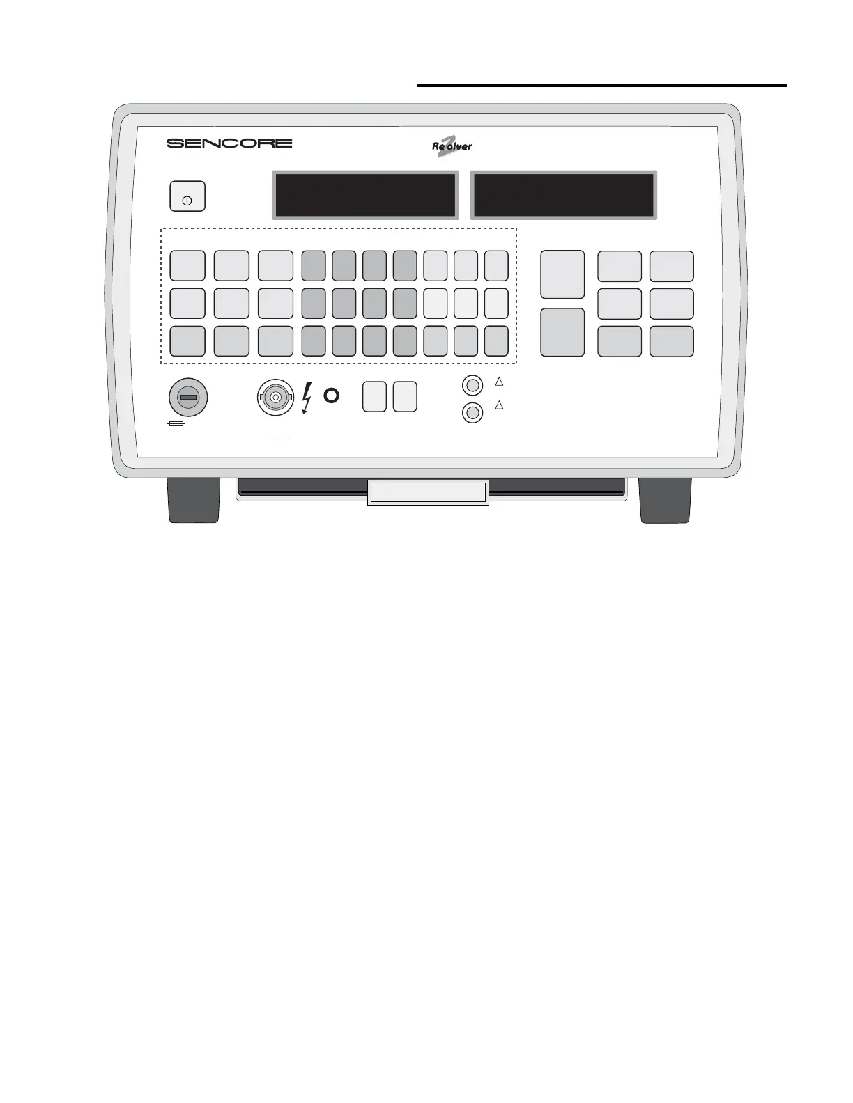
Fig. 10: Controls used for entering component data.
To perform the automatic GOOD/BAD tests with the
LC103, you must enter data about the component under
test. (All component tests can be performed without
entering component data if automatic GOOD/BAD test
indications are not desired). The component data is used
by the LC103 to make GOOD/BAD determinations.
The component data, which can be entered into the
LC103, includes: component type, value, tolerance, and
rated working voltage for capacitors, and component
type, value, and tolerance for inductors. These
parameters are usually marked on the component, or can
be determined by looking the component up in a parts
list or replacement guide. The APPLICATIONS section
of this manual contains information on how to identify
capacitor and inductor types.
NOTE: All component data can be cleared by pressing
the "CLR" button twice on the gray COMPONENT
PARAMETERS keypad.
To enter component type:
1. Press the desired COMPONENT TYPE button. Use
the beige color-coded buttons when checking
capacitors and the blue buttons when checking
inductors.
2. The COMPONENT TYPE selected will be shown on
the COMPONENT SETUP display.
To enter component value:
1. Enter a number, up to 6 characters, equal to the value
of the capacitor or inductor. Each character will
appear in the display as a key is pushed.
a. The LC103 accepts numbers up to 6 places before
the decimal. (Example: “123456”).
b. The LC103 accepts numbers up to 4 places after
the decimal. (Example: “1.2345”).
c. Push the "CLR" button once to clear the value
entry and start over.
2. Enter the desired capacitor value multiplier or
inductor value multiplier.
a. The capacitor value range is 1 pF to 20 F. The
inductor value range is 0.1 uH to 20 H.
b. The LC103 accepts non-conventional value
notations, such as ".00001 F”, “00002 uF", or
"100000 pF".
3. After entering the multiplier, the value will now be
shown on the COMPONENT SETUP display. The
LC103 is now ready for the next parameter entry.
4. To change an entered value parameter, repeat steps 1
& 2.
!
!
LC103
COMPONENT SETUP
COMPONENT TYPE
LEAD FUSE TEST LEAD LEAD ZERO
NUMERIC INPUT ENTER IN-CIRCUIT OUT-OF-CIRCUIT
COMPONENT PARAMETERS COMPONENT TESTS
COMPONENT TEST RESULTS
CAPACITOR & INDUCTOR ANALYZER
POWER
HOLD FOR
BATTERY
TEST
ALUMINUM
LYTICS
DOUBLE
LAYER
LYTICS
HIGH R
DOUBLE
LAYER
1 2 3 4 pF µF F
CAPACITOR
GOOD/BAD
INDUCTOR
GOOD/BAD
CAPACITOR
VALUE
CAPACITOR
ESR
CAPACITOR
LEAKAGE
INDUCTOR
RINGER
DIELECTRIC
ABSORPTION
INDUCTOR
VALUE
+ % - % V
µH mH H
5678
90
•
CLR
ALL
OTHER
CAPS
SWITCHING
TRANS-
FORMERS
TANTALUM
CAPS
CERAMIC
CAPS
YOKES &
FLYBACKS
COILS
1A, TT
2 AG, SLO BLO
0-1000 V
500 mA
REMOTE
OPEN
RANGES: 1pF to 20 F, 0.1 µH to 20 H Patent Nos. 4258315, 4267503, 4795966, 4825147, 5717338, Others Pending
WARNING: Flashing light indicates 25-1000V
applied to test leads when leakage button is pressed.
STOP TESTING: Protection circuit or fuse is open.
Capacitor being tested may be charged. Carefully
discharge capacitor and check fuse.
SHORT
F
U
S
E
F
U
S
E
PULL CHART
Alum Lytic 100
μ
F
+20% -20% 50V
102.6
μ
F 0.89Ω
GooD