21
To measure capacitor leakage:
1. Connect the capacitor to the test leads. If the
capacitor is polarized, connect the red test clip to the
“+” capacitor terminal and the black test clip to the
“-” terminal.
2. Enter the rated working voltage of the capacitor.
———————— WARNING —————————
The LC103 is designed to be operated by a
technically trained person who understands the
shock hazard of up to 1000 volts applied to the test
leads during the capacitor leakage test. DO NOT
hold the capacitor in your hand, or touch the test
leads or capacitor leads when making the leakage
test.
———————— ATTENTION ————————
Le LC103 est fait pour être utilize par une personne
qui est techniquement capable et qui comprend les
chocs que peut produire l’équipement (jusqu’à 1000
V) lorsque le test de fuite est utilize. NE PAS tenir la
capacité dans la main ou toucher la sonde ou la patte
de la capacité pendant le test de fuite.
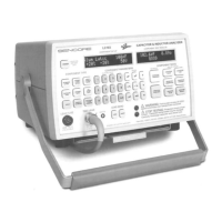
3. Press the CAPACITOR LEAKAGE button and read
the amount of leakage in the COMPONENT TEST
RESULTS display.
4. Compare the measured leakage to the maximum
allowable amount listed in the Leakage Charts on
pages _ and _ for the type, value, and voltage rating
of the capacitor you are testing.
NOTE: By entering the Component Type and Value
parameters for the capacitor, the LC103 will
automatically display the measured leakage along with
the same GOOD/BAD indication as the Leakage Charts.
Voltage will be applied to the capacitor as long as the
CAPACITOR LEAKAGE button is pressed, and the
leakage readings will decrease as the capacitor continues
to charge. Some capacitors may take a few seconds to
charge up to the applied voltage. The display will show
a bar graph estimating the charge on the capacitor.
Continue to depress the CAPACITOR LEAKAGE
button until the leakage reading drops below the
maximum allowable amount listed in the Leakage Chart.
When the CAPACITOR LEAKAGE button is released,
the LC103 discharges the capacitor through an active
load. The LC103 contains safety circuits which sense the
voltage across the test leads. Therefore, when you
release the CAPACITOR LEAKAGE button after
checking a large value capacitor, or after applying a high
leakage voltage, the display may show
“DISCHARGING CAPACITOR” and the STOP
TESTING alarm may activate until the voltage is gone
from the test leads. All data input and test buttons will be
locked out until the display returns to “Ready.”
Leakage In Paper, Mica and Film Capacitors
Paper, mica and film capacitors should have extremely
small amounts of leakage. Measuring any leakage when
checking these types of capacitors indicates a bad
component. The leakage test takes several seconds to
charge the capacitor before an accurate leakage reading
is displayed.
Leakage In Ceramic Capacitors
Leakage in ceramic capacitors is generally very low.
Ceramic disc capacitors, however, may have small
amounts of normal leakage. Ceramic disc capacitors
with voltage ratings above 50 WVDC should have less
than 1 uA of leakage. Some discs with working voltages
less than 50 WVDC may have a lower insulation
resistance, and therefore may show somewhat more
leakage, depending upon manufacturer. In general, a 10
WVDC ceramic disc capacitor may show as much as 16
uA of leakage, and 25 WVDC ceramic disc may read up
to 2.5 uA of leakage and still be considered good.
Leakage In Aluminum Electrolytics
Because of their larger value and higher leakage
characteristics, aluminum electrolytic capacitors may
take longer to charge. When the capacitor reaches full
charge, the LC103 displays a current and resistance
reading. The leakage current progressively decreases as
the dielectric reforms. Initial reading properly indicates
leakage current. Compare readings to the maximum
amount shown in leakage chart.
Leakage In Tantalum Electrolytics
Tantalum electrolytic capacitors have much lower
leakage than aluminum electrolytics of the same size and
voltage rating. Therefore, tantalum lytics will give a
leakage reading in a much shorter time than an
aluminum lytic - typically within 2 to 5 seconds.
Compare the measured leakage with the amounts shown
in the leakage charts to determine if the capacitor is good
or bad.
Leakage In Non-Polarized (Bi-Polar) Electrolytics
Electrolytic capacitors which are non-polarized should
be checked for leakage in both directions. This requires
that you measure leakage twice, reversing the LC103 test
lead connections for the second test. The maximum
allowable leakage for a non-polarized electrolytic in
either direction is twice that of a similar polarized
electrolytic of similar capacitance value and voltage
rating.

 Loading...