7
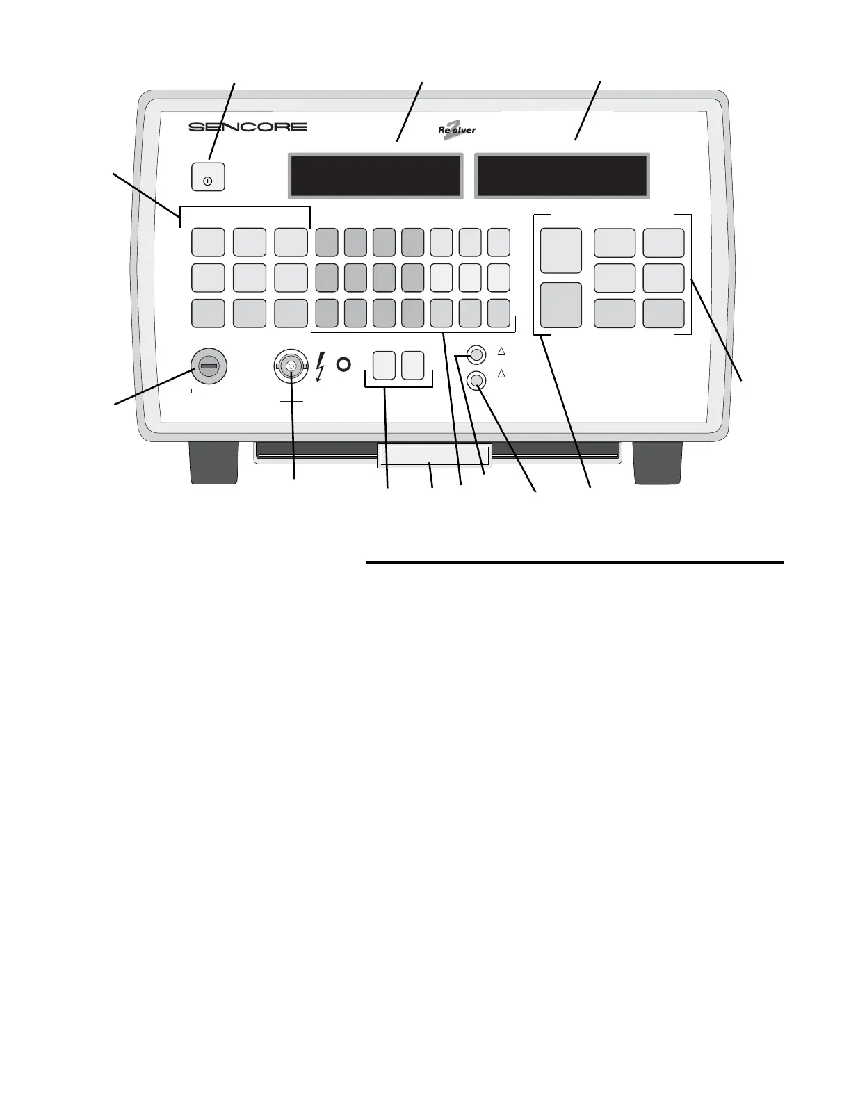
Fig. 1: Location of front panel controls.
FRONT PANEL CONTROLS
1. POWER Button – Press to power unit on or off. Press
and hold for Battery Test.
2. COMPONENT TYPE Buttons – Use to select
component type to be tested.
a-f: Press to select desired capacitor type
g-i: Press to select desired inductor type
3. LEAD FUSE – Unscrew for access to the test lead fuse.
4. TEST LEAD Jack – BNC type jack to connect test leads
to unit.
5. LEAD ZERO Buttons – Use to balance out test lead
impedance.
a. OPEN – Press to compensate for tet lead capacitance
with test leads open.
b. SHORT – Press to compensate for test lead
inductance and resistance with test leads shorted.
6. PULL CHART – Provides simplified operating
instructions and quick reference tables.
7. COMPONENT PARAMETERS Buttons – Use to enter
component parameters for limit testing.
a-k: Use to enter numerical portion of parameters.
l: CLR: Press once to clear numeric input. Press twice
to clear all component parameters.
m-o: Capacitor Value Multipliers: Use after numeric input
to enter capacitor value.
p-q: Percentage buttons: Use after numeric input to enter
component tolerance.
r: Volts: Use after numeric input to enter voltage for
capacitor leakage test.
s-u: Inductor Value Multipliers: Use after numeric input
to enter inductor value.
8. WARNING LED – Flashes to indicate leakage voltage
has been set to 25 volts or more. Voltage is only present
when CAPACITOR LEAKAGE button is pressed.
9. STOP TESTING LED – Flashes along with an audible
alarm and “FUSE OPEN” message to indicate test lead
fuse is open.
10. IN-CIRCUIT Test Buttons – Press to test capacitors or
inductors in-circuit.
11.
OUT-OF-CIRCUIT Test Buttons
a. Capacitor GOOD/BAD – Press to measure
capacitor value and ESR in-circuit.
b. Inductor GOOD/BAD – Press to measure
inductance value in-circuit.
c. Dielectric Absorption – Press to measure percentage
of dielectric absorption.
d. Capacitor Leakage – Press to measure the amount
of leakage after a voltage has been entered with the
COMPONENT PARAMETERS keypad (6).
e. Inductor Value – Press to measure inductance value.
f. Inductor Ringer – Press to activate Ringer test after
selecting inductor type (2g-i).
12. COMPONENT TEST RESULTS Display – Displays
the resultant value of test.
13. COMPONENT SETUP Display – Displays entered
component type, value, tolerance, and voltage rating.
!
!
LC103
COMPONENT SETUP
COMPONENT TYPE
LEAD FUSE TEST LEAD LEAD ZERO
NUMERIC INPUT ENTER IN-CIRCUIT OUT-OF-CIRCUIT
COMPONENT PARAMETERS COMPONENT TESTS
COMPONENT TEST RESULTS
CAPACITOR & INDUCTOR ANALYZER
POWER
HOLD FOR
BATTERY
TEST
ALUMINUM
LYTICS
DOUBLE
LAYER
LYTICS
HIGH R
DOUBLE
LAYER
1 2 3 4 pF µF F
CAPACITOR
GOOD/BAD
INDUCTOR
GOOD/BAD
CAPACITOR
VALUE
CAPACITOR
ESR
CAPACITOR
LEAKAGE
INDUCTOR
RINGER
DIELECTRIC
ABSORPTION
INDUCTOR
VALUE
+ % - % V
µH mH H
5678
90
•
CLR
ALL
OTHER
CAPS
SWITCHING
TRANS-
FORMERS
TANTALUM
CAPS
CERAMIC
CAPS
YOKES &
FLYBACKS
COILS
1A, TT
2 AG, SLO BLO
0-1000 V
500 mA
REMOTE
OPEN
RANGES: 1pF to 20 F, 0.1 µH to 20 H Patent Nos. 4258315, 4267503, 4795966, 4825147, 5717338, Others Pending
WARNING: Flashing light indicates 25-1000V
applied to test leads when leakage button is pressed.
STOP TESTING: Protection circuit or fuse is open.
Capacitor being tested may be charged. Carefully
discharge capacitor and check fuse.
SHORT
F
U
S
E
F
U
S
E
PULL CHART
Alum Lytic 100
μ
F
+20% -20% 50V
102.6
μ
F 0.89Ω
GooD
a
b
c
d
e
f
g
h
i
a b c
d
e f g
h
i j k
l
m
n o
p
q r
s
t u
11312
2
3
4
5
6
7
8
9
10
11