48
APPENDIX
INTRODUCTION
The capacitor is one of the most common components
used in electronics, but less is known about it than any
other. The following is a brief explanation of the
capacitor, how it works, and how it fails.
CAPACITOR THEORY
The basic capacitor is a pair of metal plates separated by
an insulating material called the dielectric. The size of
the plates, the type of dielectric, and the thickness of the
dielectric determines the capacity. To increase capacity,
you can increase the size of the plates, increase the
number of plates, use a different or thinner dielectric.
The closer the plates, or the thinner the dielectric, the
larger the capacity for a given size plate. Because flat
plates are rather impractical, capacitors are generally
made by putting an insulating material (dielectric)
between two foil strips and rolling the combination into
a tight package or roll.
Fig. 35: Many capacitors are made of foil separated
by a dielectric and rolled into a tight package.
The old explanation of how a capacitor works had the
electrons piling up on one plate forcing the electrons off
of the other to charge a capacitor. This made it difficult
to explain other actions of the capacitor. Faraday’s
theory more closely approaches the way a capacitor
really works. He stated that the charge is in the dielectric
material and not on the plates of the capacitor. Inside the
capacitor's dielectric material, there are tiny electric
dipoles. When a voltage is applied to the plates of the
capacitor, the dipoles are stressed and forced to line up
in rows creating stored energy in the dielectric. The
dielectric has undergone a physical change similar to
that of soft iron when exposed to current through an
inductor when it becomes a magnet. If we were able to
remove the dielectric of a charged capacitor, and then
measure the voltage on the plates of the capacitor, we
would find no voltage. Reinserting the dielectric and
then measuring the plates, we would find the voltage that
the capacitor had been charged to before we had
removed the dielectric. The charge of the capacitor is
actually stored in the dielectric material. When the
capacitor is discharged, the electric dipoles become re-
oriented in a random fashion, discharging their stored
energy.
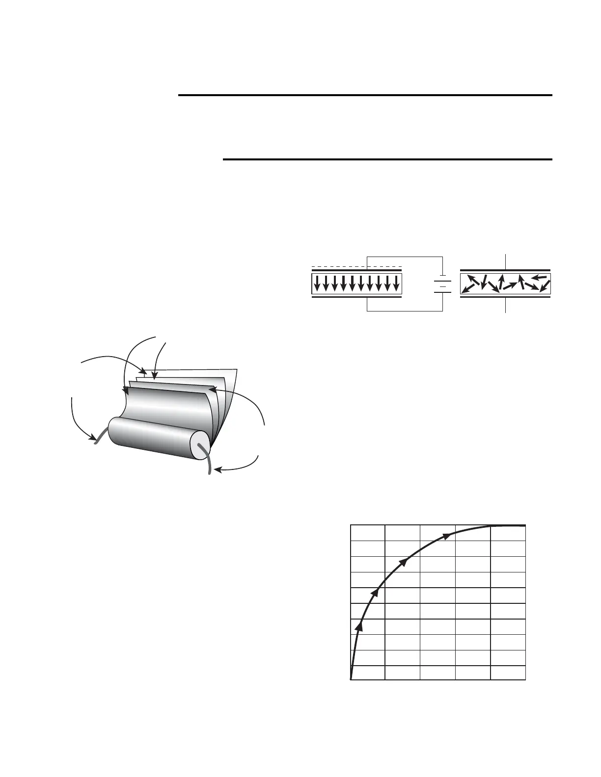
Fig. 36: Applying a potential to a capacitor causes
the dipoles in the dielectric to align with the applied
potential. When the capacitor discharges, the
dipoles return to an unaligned, random order.
When a capacitor is connected to a voltage source, it
does not become fully charged instantaneously, but takes
a certain amount of time. The time required for the
capacitor to charge is determined by the size or capacity
of the capacitor, and the resistor in series with the
capacitor or its own internal series resistance. This is
called the RC time constant. Capacity in Farads
multiplied by resistance in Ohms equals the RC time
constant in seconds. The curve of the charge of the
capacitor is the RC charge curve.
Fig. 37: Capacitors follow an RC charge time as they
charge to the applied voltage.
Foil Plate
for this
end
Foil Plate
for this
end
Dielectric
+ + + + + + + + + + + + + + + + + + + +
Charged Capacitor Uncharged Capacitor
100
90
80
70
60
50
40
30
20
10
0
ORC 1RC 2RC 3RC 4RC 5RC