10
WEB600 User’s Manual
INSTALLATION AND CONFIGURATION
PHYSICAL DESCRIPTION
The Web600 is housed in a 5.5”w x 3.7”h x 1.4”d enclosure, which can be easily wall mounted.
LAYOUT
The Web600 has connections for six sensor inputs, an ethernet port, battery backup, and 5VDC power.
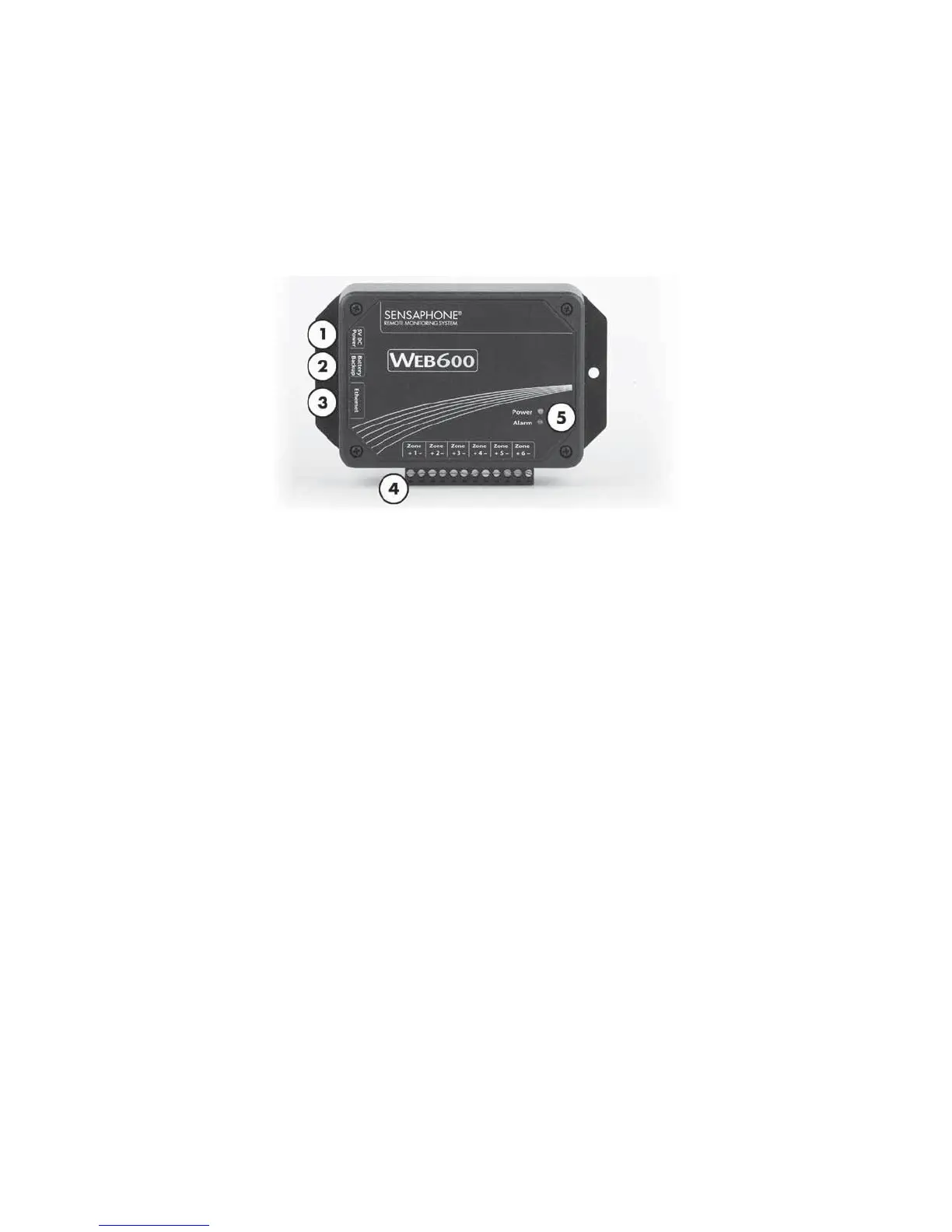
See figure below:
Figure 1: Front Panel Layout of the Web600
1) 5V DC Power Jack
2) Battery Backup Connector
3) Ethernet Jack
4) Sensor Input Terminal Strip
5) Status LEDs
RJ-45 10/100BASE-T ETHERNET PORT
This jack is for connecting to your network so that the Web600 can send alarm messages and display it’s
webpage. Two LEDs indicate when the Web600 has a valid link (green) and transmitted/received data
(yellow).
SENSOR INPUTS
The sensor inputs labeled zones 1-6 are designed to interface with normally open/normally closed devic-
es, 2.8K or 10K temperature sensors and 4-20mA transducers.
POWER ON LED (GREEN)
This light indicates that the Web600 unit is powered and operational.
ALARM LED (RED)
The Alarm LED is a visual indication that an alarm exists.