41
Appendix C: Modbus® specifications
MODBUS® NOTES
MODBUS® ADDRESSES
Address Ranges
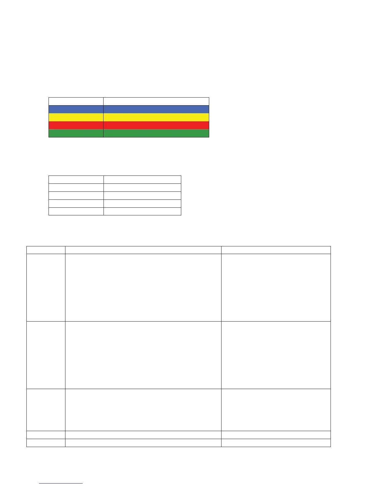
The Modbus® address ranges are laid out according to the following color-coded table.
The format below is TxDDDDD where “T” is the address type (bit/word, read-write/
read-only) and DDDDD is a 5 digit decimal base number from 0 to 65535.
Modbus® Mode Modbus® Address Range
bit, read-write 0x00000 - 0x65535
bit, read-only 1x00000 - 1x65535
word, read-only 3x00000 - 3x65535
word, read-write 4x00000 - 4x65535
The memory types map to the Modbus® commands as shown in the following table.
The Web600 supports Modbus® conformance classes 0 and 1.
Address Type Modbus® Commands
0 1, 5, 15
12
34
4 3, 6, 16
Address Calculation
Modbus® Address calculations are performed according to the following table:
Type Calculation Notes
Inputs
BASE + (OFFSET * INPUT_NUMBER)
The input number is as follows:
Zone 1 = 0
Zone 2 = 1
Zone 3 = 2
Zone 4 = 3
Zone 5 = 4
Zone 6 = 5
Power = 7
Battery = 8
Profiles
BASE + (OFFSET * PROFILE_NUMBER)
The profile number is as follows:
Profile 1 = 0
Profile 2 = 1
Profile 3 = 2
Profile 4 = 3
Profile 5 = 4
Profile 6 = 5
Profile 7 = 6
Profile 8 = 7
Contacts
BASE + (OFFSET * ((PROFILE_NUMBER * 6) +
CONTACT_NUMBER))
The contact number is as follows:
Contact 1 = 0
Contact 2 = 1
Contact 3 = 2
Contact 4 = 3
Network
BASE
System
BASE