Doc No. 006-0211-00 Rev AD Page 10 of 62
Figure 3. Gauge stabbed into motor base.
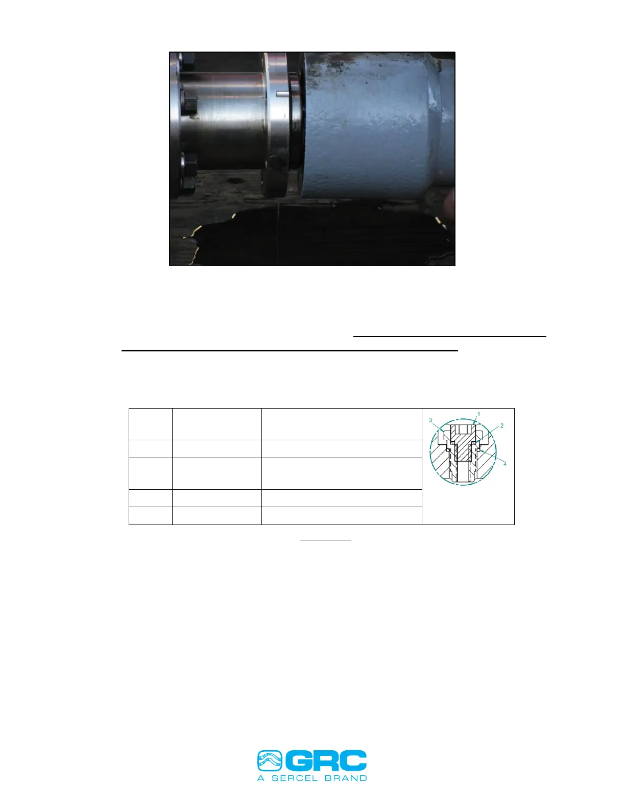
3. Once the sensor has been stabbed as far as shown in Figure 3, place one of
the motor base bolts through the bolt hole and into the sensor motor head to
make sure that the bolt holes are lined up. DO THIS BEFORE PROCEEDING
TO STAB THE SENSOR FULLY ONTO THE MOTOR BASE.
4. Use of the fill and plug valve to fill the gauge with oil from the gauge plug. Most
customers do not use the fill and plug valve on the gauge and use the one
located on the motor. Below is a description of the plug:
GASKET, VENT & DRAIN
LEAD SEAL
Note: Both gaskets listed above are single-use components. Item 3 (valve) should be
torqued to 210 in-lbs and Item 1 (plug) should be torque to 100 in-lbs.
5. Connect the SCOUT to the motor and gauge assembly. Connect the red wire
(gauge signal) to one of the motor lead power connections and the white or
black wire to the motor housing.
6. Record the parameter readings on the Fortress ESP Sensor Checklist.