Doc No. 006-0211-00 Rev AD Page 21 of 62
SPS-1500 Installation
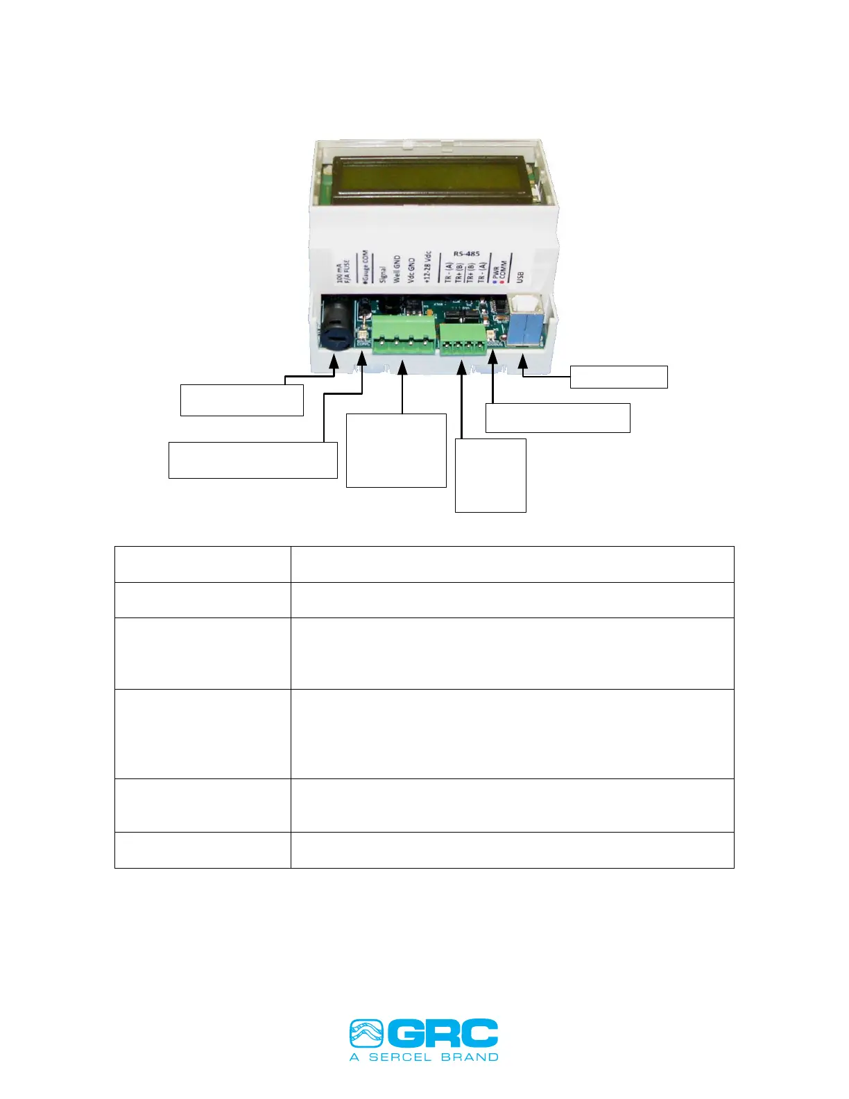
Illustrations on how to install the SPS-1500 is shown in Figure 17 below.
USB Connection
Blue LED: Power
Red LED: Modbus Traffic
RS-485/422
1: TR -
2: TR +
3: TR +
4: TR -
Power/Gauge
1: Gauge Signal
2: Well Ground
3: Vdc Ground
4: Vdc +12 to 28V
Orange LED: Gauge Data Byte
Green LED: Gauge Data BIt
Gauge Fuse: 5x20mm
100mA Fast Acting
Gauge signal fuse, 100mA fast acting 5x20mm, GRC P/N 043-
0042-00
Flashes green for every gauge data bit received
Flashes orange for every gauge data byte received
1. Gauge Signal
2. Gauge Signal Return/Wellhead Ground
3. Vdc Ground
4. Vdc Power +12V to 28V DC
RS-485 / RS422
Modbus Slave
RS-485: Install (2) Jumpers | RS-422: Remove (2) Jumpers
1. TR - | 1. T-
2. TR + | 2. T+
3. TR + | 3. R+
4. TR - | 4. R-
Power/Modbus
Bi-Color LED
Solid blue when power is connected
Blinks Red when a ModBus request is received
Modbus and firmware updating via USB Virtual COM Port
Figure 17. SPS-1500 Connections.