Doc No. 006-0211-00 Rev AD Page 47 of 62
4-20 mA CARD INSTALLATION AND CONFIGURATION
Installing 4-20mA optional cards into the Scout-3000
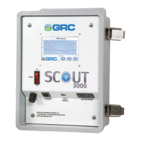
Figure 42 labels the main components of the Scout-3000. The procedure follows.
Figure 42. Scout-3000 Internal Subcomponent Identification.
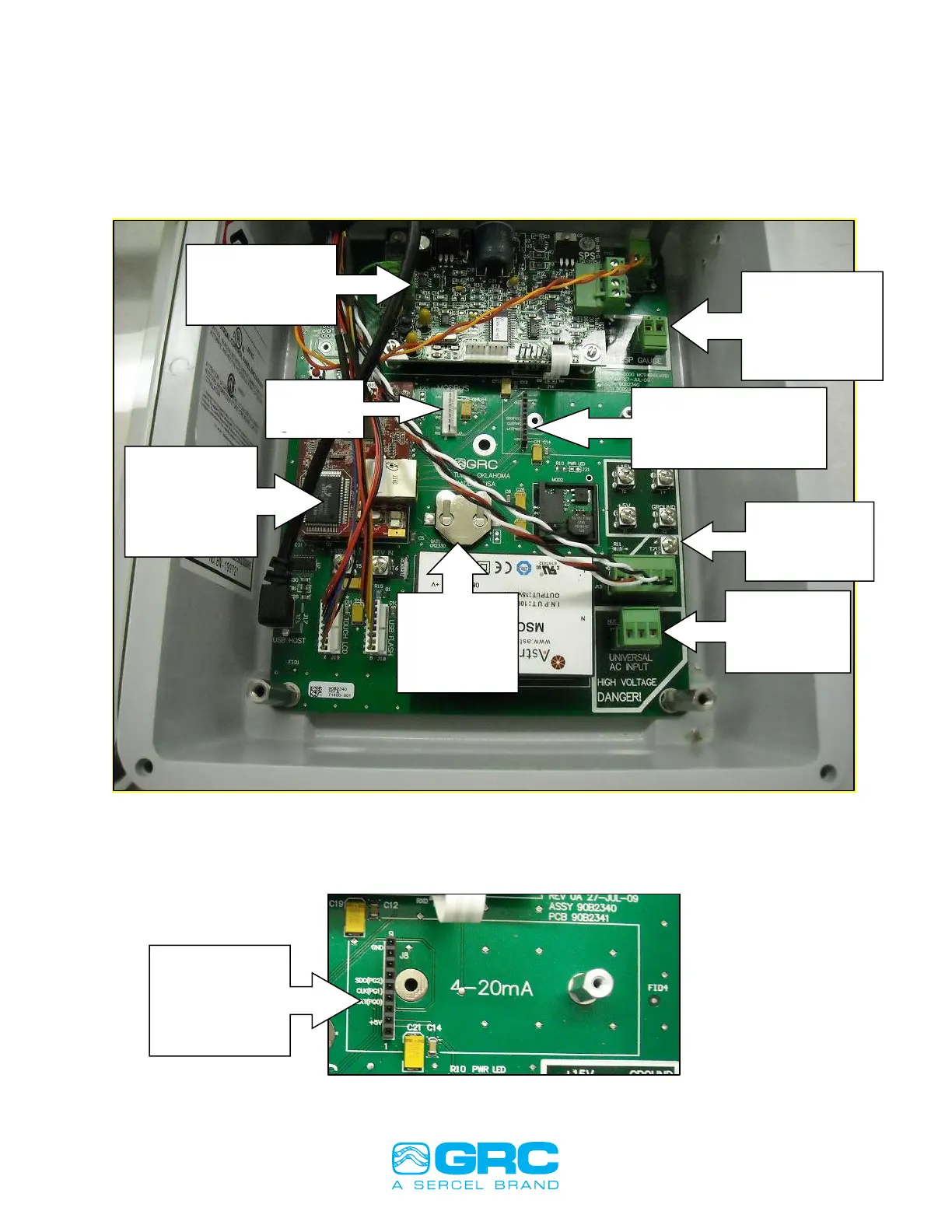
1. Install a 4-20 mA card 99B470 into J8 (4-20 mA) connector on the Scout mother
board and secure it with the standoff included in kit as shown in Figures 43 & 44.
Figure 43. 4-20 mA module.
4-20mA
Current Loop
Module
Connection
SPS Module
(Gauge Power
Supply)
Gauge Signal
and Signal
Return
Connections
4-20mA Current
Loop Module
Connection
AC Power
Input
Connection
Graphing
Memory
Backup
Battery
RCM
(control
module for
Scout-3000)