EasyManuals Logo

Sercel GRC ESP-Series User Manual

Sercel GRC ESP-Series
63 pages
To Next Page IconTo Next Page
To Previous Page IconTo Previous Page
Page #48 background imageLoading...
Page #48 background image
Doc No. 006-0211-00 Rev AD Page 48 of 62
Figure 44. Standoff placement.
2. Check switch position on 4-20 mA card to verify it is configured properly as
shown in Figure 45.
Figure 45. Switch Position.
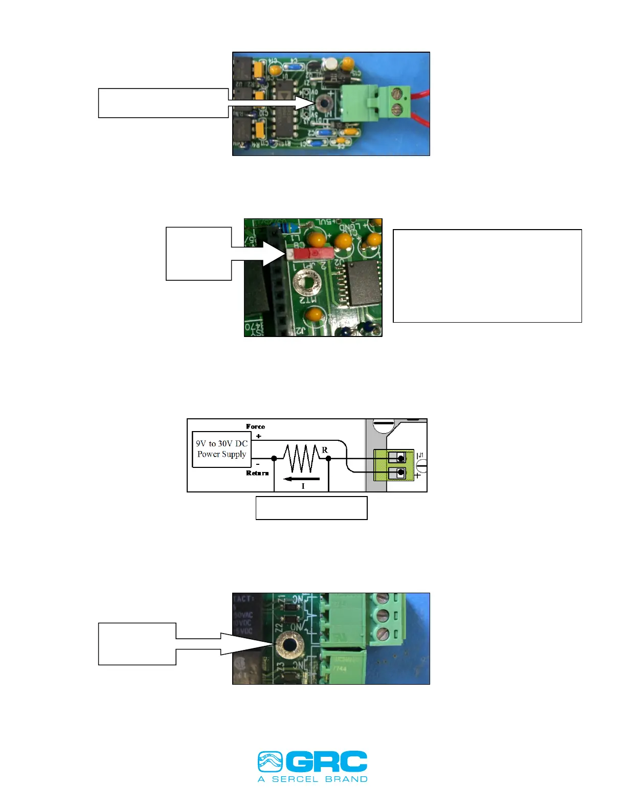
3. Wire 4-20 mA current loop with power supply. Figure 46.
Figure 46.
4. Install Relay card and secure with 4-40 screw provided. Figure 47.
Figure 47. Screw position.
4-20mA
Switch
position
Install standoff here
4-20 mA Receiver
Install
screw here
If a second 4-20 mA card is
installed, the upper card will
have this switch in the opposite
position. The lower card will
have the switch in the position
shown.

Table of Contents

Questions and Answers:

Question and Answer IconNeed help?

Do you have a question about the Sercel GRC ESP-Series and is the answer not in the manual?

Sercel GRC ESP-Series Specifications

General IconGeneral
BrandSercel
ModelGRC ESP-Series
CategoryMeasuring Instruments
LanguageEnglish

Related product manuals