Doc No. 006-0211-00 Rev AK Page 17 of 33
INSTALLING THE SURFACE INTERFACE EQUIPMENT
Wiring Detail
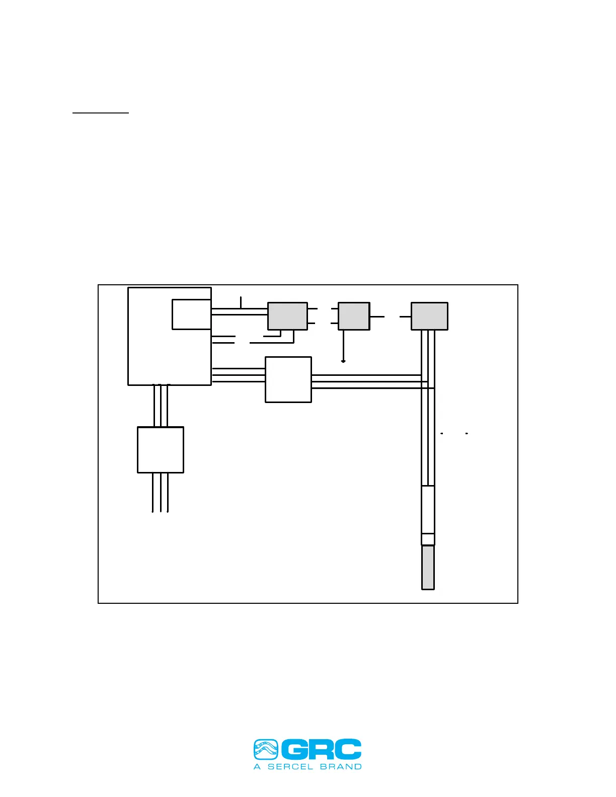
FIGURE 16 shows a typical wiring and installation schematic for the ESP surface
equipment.
ESP Gauge and Surface Control Interface Diagram Components
1. ESP Gauge Surface Readout Interface (SPS-1500/Scout-3000/Data Pro)
2. Surge Panel Equipment (Surge Suppressor and Fuse Protection #90D2215 or
#90B2175)
3. Surface Choke - 3-phase choke (P/N 99B990)
4. Motor Head Adapter and WYE point connection
5. Downhole Choke and Sensor Module (Gauge)
VSD
Controller
ESP Gauge
Interface
Modbus or Analog communication
15 VDC
Earth Ground
Gauge
Signal
Gauge
Ground
Surge
Panel
Well Head
Ground
Gauge
Signal
Y-point
Surface
Choke
Motor and Pump
Choke and Sensor
Line Service
Transformer
Power Source
3-Phase
Motor
Cable
Or AC for Scout
Motor Head Adapter
and WYE
Step-Up
Transformer
Figure 16: Surface System Wiring Diagram