Doc No. 006-0211-00 Rev AK Page 5 of 33
BENCH TESTING AND VERIFICATION PROCEDURES
Note: Bench test and verification procedures are applicable to all ESP sensors.
Tools Required
Power Supply 110 VAC/12-24VDC
Surface Readout (Scout-3000, SPS-1500, Data Pro, Field Test Box)
Signal and Ground wires
Alligator Clips
Simpson 260 analog type meter
Fluke 1550C insulation tester
Process Steps for Bench Test and Verification
1. To prevent injury, proper PPE should always be worn. Use caution when
working near or handling equipment. Utilize proper lifting techniques to
prevent injuries to personnel or equipment.
2. Remove the top shipping cap from the ESP Sensor.
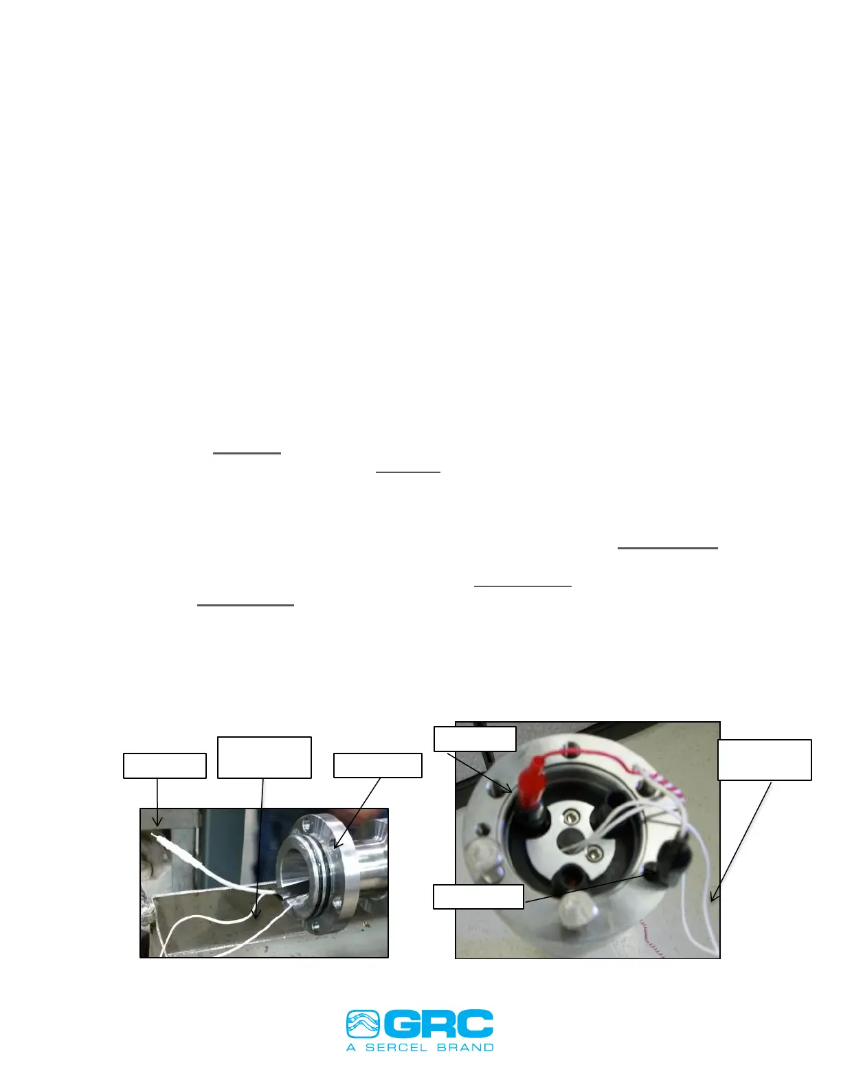
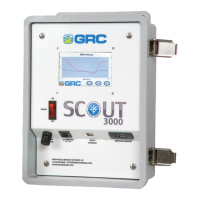
3. Connect a signal wire from the Surface Readout to the signal wire on the
sensor Figure 1, or if using a WYE Point adapter connect to one of the three
pins inside the WYE adapter Figure 2. Connect the ground wire to the sensor
housing. Connect a motor RTD to the two white motor temperature wires.
4. Power on the Surface read out.
5. Data will display on the Surface Readout in approximant 2-5 minutes.
6. Record the parameter readings on the ESP Sensor Checklist; APPENDIX 3 of
this manual, for test verification records.
7. ESP Sensor Pass/Fail Criteria is shown in APPENDIX 5.
8. See APPENDIX 6 SPS-1500 Synchronization and Startup for the complete
SPS-1500 startup sequence.
Figure 1: I-Wire Connection Figure 2: WYE Connection