Doc No. 006-0211-00 Rev AK Page 26 of 33
APPENDIX 4
Surface Read Out Device Specifications
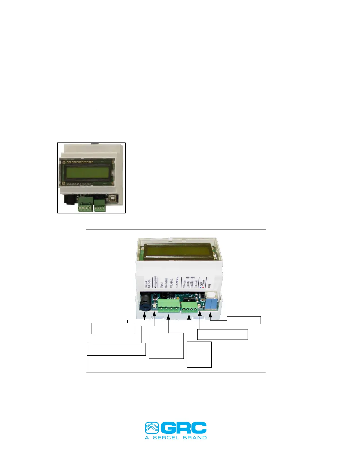
SPS-1500
The SPS-1500 includes a 2-Line Character LCD readout for display of real-time
downhole data. A USB interface is also supplied for Modbus via USB monitoring of the
downhole gauge. 24VDC is required to power the SPS-1500.
See APPENDIX 6 SPS-1500 Synchronization and Startup for the complete SPS-1500
startup sequence.
Figure 23: SPS-1500
USB Connection
Blue LED: Power
Red LED: Modbus Traffic
RS-485/422
1: TR -
2: TR +
3: TR +
4: TR -
Power/Gauge
1: Gauge Signal
2: Well Ground
3: Vdc Ground
4: Vdc +12 to 28V
Orange LED: Gauge Data Byte
Green LED: Gauge Data BIt
Gauge Fuse: 5x20mm
100mA Fast Acting
Figure 24: SPS-1500 Connections
SPS-1500 Specifications:
• Small footprint DIN rail mount
enclosure
• Enclosure size: 3-1/2” x 3-1/2” x 2-1/2”
• 2-Line LCD display with scrolling
update of downhole sensor data
• 2 Multi-color displays for immediate
communication and downhole tool
status
• Single ESP gauge interface with field
replaceable fuse.
• Modbus communication via RS485,
RS-232, RS422
• USB available for downhole monitoring
to PC
• 12-24VDC power required, 200mA
• Configurable via free Memory Tools
software
• Operating Temperature: -10ºC to
+70ºC