Section 2 Installation Instructions
Part Number 020005256 5/15 2-19
Internal Carbonator Connections
1. Connect the carbonator pump deck (power supply) to
the valve connection (if equipped) at the Drop-In. The
wires are marked appropriately. Check the electric key
switch on the side of the tower. The key should be in the
“OFF” (vertical) position.
2. The outside edge of the chest flange must be sealed to
the counter top. Apply a generous amount of sealant to
the underside of the outside edge of the flange.
3. Carefully remove the two blocks of wood from under
the flange. The Drop-In will then sit flat on the
counter top.
4. Wipe excess sealant from around the outer portion
of the flange.
5. Check to be sure the entire flange edge is sealed to
the counter top.
6. Apply water and syrup pressure to the beverage
system. Check for leaks to the system and repair
any leaks found.
7. Purge air from the carbonator tank.
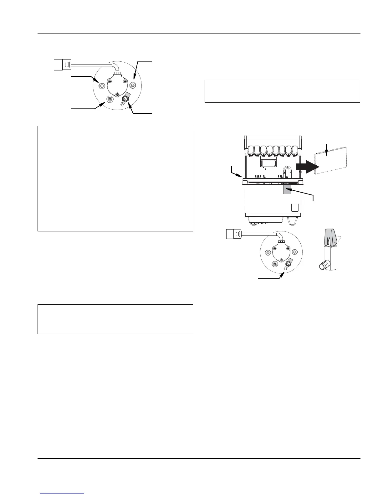
Purging Air from the Carbonator Tank
1. Unit must be properly plumbed before purging the
carbonator tank. (See Plumbing Diagrams Page 2 -
12), without power, and with the CO
2 turned OFF.
2. Remove the panel behind the drain pan to gain
access to the carbonator tank and open the vent on
the carbonator pressure relief valve.
3. Turn on the water to the unit, fill the carbonator with
water and close the vent on the carbonator pressure
relief valve when water begins to escape the vent.
4. Plug the power cord from the unit into a power outlet
and turn the key switch for the valves to the “ON”
position and operate any valve to remove all the air from
the water lines.
5. Plug power cord (from the carbonator motor) into the
unit power cord assembly and connect the power
supply cord from the carbonator deck box into a
power outlet.
6. Perform monthly cleaning and sanitation, See
Monthly Cleaning Page 4 - 2.
7. Fill the chest with ice. Allow the coldplate to chill the
beverage tubing inside the coldplate.
NOTE: Clean your work area while waiting for the cold
plate to cool.
8. Verify and set system pressures.
The CO2 connection for the internal carbonator is located with
the coldplate connections. (See plumbing diagram.) Check valve
must be installed to plain water connection “B”. Contact factory if
not installed. Valves are read from right to left.
The water supply must first be connected to the carbonator pump
(not shown) before plumbing to connections “A” shown on the
plumbing diagram.
The carbonator pump deck must be within six (6) feet of the
dispenser for optimum performance. A check valve must be
installed in the water supply line 3 feet from the non-carbonated
water connection “PW”. Contact factory if not installed.
The unit must be sealed to the counter to comply with
NSF requirements.
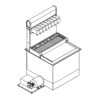
Pressure
Relief Valve
Water Outlet
Water Inlet
CO
2 Inlet
Do not energize the unit or turn on the CO2 to the unit.
Panel
Internal
Carbonator
Tank
Drain Pan
Pressure
Relief Valve
Open Position