Section 2 Installation Instructions
Part Number 020005256 5/15 2-7
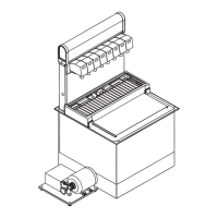
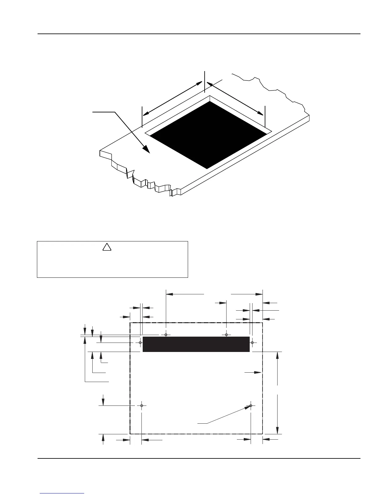
COUNTER TOP FOOTPRINTS
DI-1522 & DI/DIL-2323
1. Mark the counter top with the appropriate cut out opening
dimensions, see illustration above.
2. Check that the cut out location is approved by the
owner before any cuts are made in the counter top.
3. Compare the marked cut out with the dispenser chest
size. Double check the marked hole size to be cut.
4. Cut the marked opening in the counter top.
5. Place one block of wood on the left side of the opening
at the edge of the cut out. Place another block of wood
on the right side of the opening at the edge of the cut
out. See Placing the Unit Page 2 - 9.
CT-6
D
I
-
1
5
2
2
W
i
d
t
h
=
1
5
.
2
5
(
3
8
.
7
0
c
m
)
D
I
/
D
I
L
-
2
3
2
3
W
i
d
t
h
=
2
3
.
2
5
(
5
9
.
1
0
c
m
)
D
I
-
1
5
2
2
&
D
I
/
D
I
L
-
2
3
2
3
C
u
t
O
u
t
A
r
e
a
Counter
Top
D
I
-
1
5
2
2
D
e
p
t
h
=
2
2
.
2
5
(
5
6
.
5
0
c
m
)
D
I
/
D
I
L
-
2
3
2
3
D
e
p
t
h
=
2
3
.
2
5
(
5
9
.
1
0
Cutting the countertop may decrease its strength. Counter
should be braced to support the dispenser countertop
weight plus ice storage capacity.
12.375 in
(31.4 cm)
4.625 in (11.7 cm)
.313 in (.8 cm)
1.625 in (4.1 cm)
.313 in (.8 cm)
10.5 in (26.7 cm)
1.5 in (3.8 cm)
1.5 in (3.8 cm)
3.625 in (9.2 cm)
1.625 in (4.1 cm)
1.188 in
(3.0 cm)
1.938 in
(4.9 cm)
.250 in
(.6 cm)
Perimeter of CT-6 Base
6 Holes (See Notes)