Section 3 Operation
Part Number 020005256 5/15 3-3
CO2 SUPPLY
Note: CO
2 inlet for the internal carbonator is located
with the cold plate inlet lines.
(See plumbing diagram for exact plumbing location)
•CO2 pressure to the BIB pump is 60 to 75 psi.
• DI-1522, 2323 & DIL-2323 CO
2 pressure to the internal
carbonator is 75 psi.
• For ambient carbonated systems the CO
2 pressure to the
carbonator should be set at 100 PSI
• "Optional" A low CO
2 alarm is available on all internally
Carbonated DI series units. A RED low CO
2 light mounted
to the tower will illuminate when the CO
2 supply for the
cabonator tank starts running low.
A CO
2 cylinder delivers carbon dioxide (CO2) gas through an
adjustable CO
2 regulator to the syrup BIB pump and also to
an internal carbonator. Plain water also enters the internal
carbonator tank, and is carbonated by the regulated CO
2 gas
pressure. When a dispensing valve is opened, CO
2 pressure
exerted within the syrup BIB pump propels syrup from the
BIB, through the beverage coils, and into the dispensing
valve. Carbonated water is forced from the carbonator tank by
CO
2 pressure which pushes cold carbonated water into the
dispensing valve resulting in a carbonated drink being
dispensed. A non-carbonated drink is dispensed in the same
manner as a carbonated drink with the exception that plain
water is substituted for carbonated.
The carbonator is replenished when the carbonated water
level inside the tank drops, which in turn automatically starts
the carbonator water pump. When the water level inside the
tank has been replenished, carbonator water pump will stop.
CARBONATED WATER
Carbon Dioxide (CO
2
) leaves the storage tank and
arrives at the carbonator tank through the gas inlet.
Water supply enters the carbonator pump inlet at regular
street water line pressure (minimum 20 PSI, maximum
80 PSI, dynamic or flowing pressure). The water pump
increases the pressure of the water, which allows the
water to flow into the carbonator tank. The CO
2
and the
water mix together in the carbonator to produce the
carbonated water that is then sent to the soda dispenser.
The agitation of the water and CO
2
together in the tank
under high pressure creates the soda water. The quality
of carbonation (percent of CO
2
mixed in the water)
increases as the water temperature decreases and
exposure time increases.
The water level in the carbonator tank is controlled by a
water level control in the tank. This control turns the
pump motor off and on to maintain a preset level of liquid
in the tank. The water level control may be electronic
probes or a mechanical float.
SYRUP DELIVERY SYSTEM
Your syrup location can vary depending on the volume of
beverages served and ease of accessibility. Your
beverage system may set in a back storage room or
under the counter of the dispenser. Configurations are
almost limitless. Check the temperatures expected for
the storage location. Adverse temperatures can affect
the storage and quality of beverage products. It is
recommended the temperature of storage location
should not fall below 40°F (4°C) or rise above 90°F
(32°C).
WATER SUPPLY
For internal carbonated systems:
Incoming water supply minimum of 40 and maximum of
55 psi. If incoming (static) water supply is over 55 psi
you have to install a water regulator. If incoming
(dynamic) water pressure is under 40 psi a water
booster is required.
NOTE: The incoming water supply for the carbonator,
which is the pre-chill inlet on the plumbing diagram, must
first be ran through the carbonator pump which is
located on the carbonator pump deck (power supply).
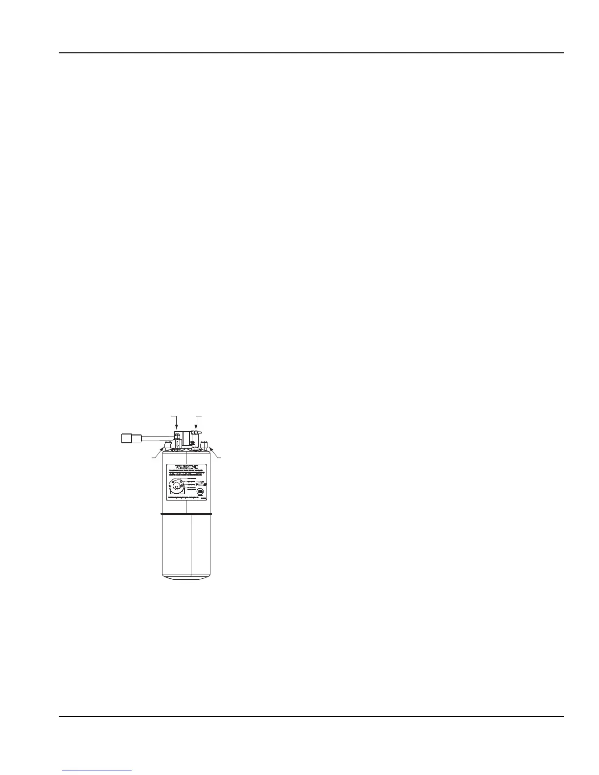
Carbonated
Water Outlet
Pressure
Relief
CO
2
inlet
120 psi max
Water Inlet