Section 2 Installation Instructions
Part Number 020003997 4/12 2-13
Step by Step Installation
GENERAL
SV Series dispensers have a stainless steel cabinet and
lighted merchandiser standard.
Beverage valves, coldplate connections, drain connections
and electrical components are front serviceable.
SPECIFICATIONS CHART
* This is the optimal pressure. When the foam is too high, decrease the
pressure; when spitting/popping is an issue, increase the pressure.
UNIT INSTALLATION
1. With countertop ready, place the dispenser in the desired location.
2. Install Selectable Ice / Flavor Magic Module.
Selectable Ice Module
The Selectable Ice Module will not be installed on
thedispenser when unit is unboxed.
A. Locate the Selectable Ice Module box in the dispenser
bin and remove the module from the box.
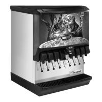
B. Remove merchandiser from dispenser by taking out the
two screws located at the top of the merchandiser. Once
the screws are removed rotate the top of the
merchandiser towards you and then lift the merchandiser
up to remove from unit.
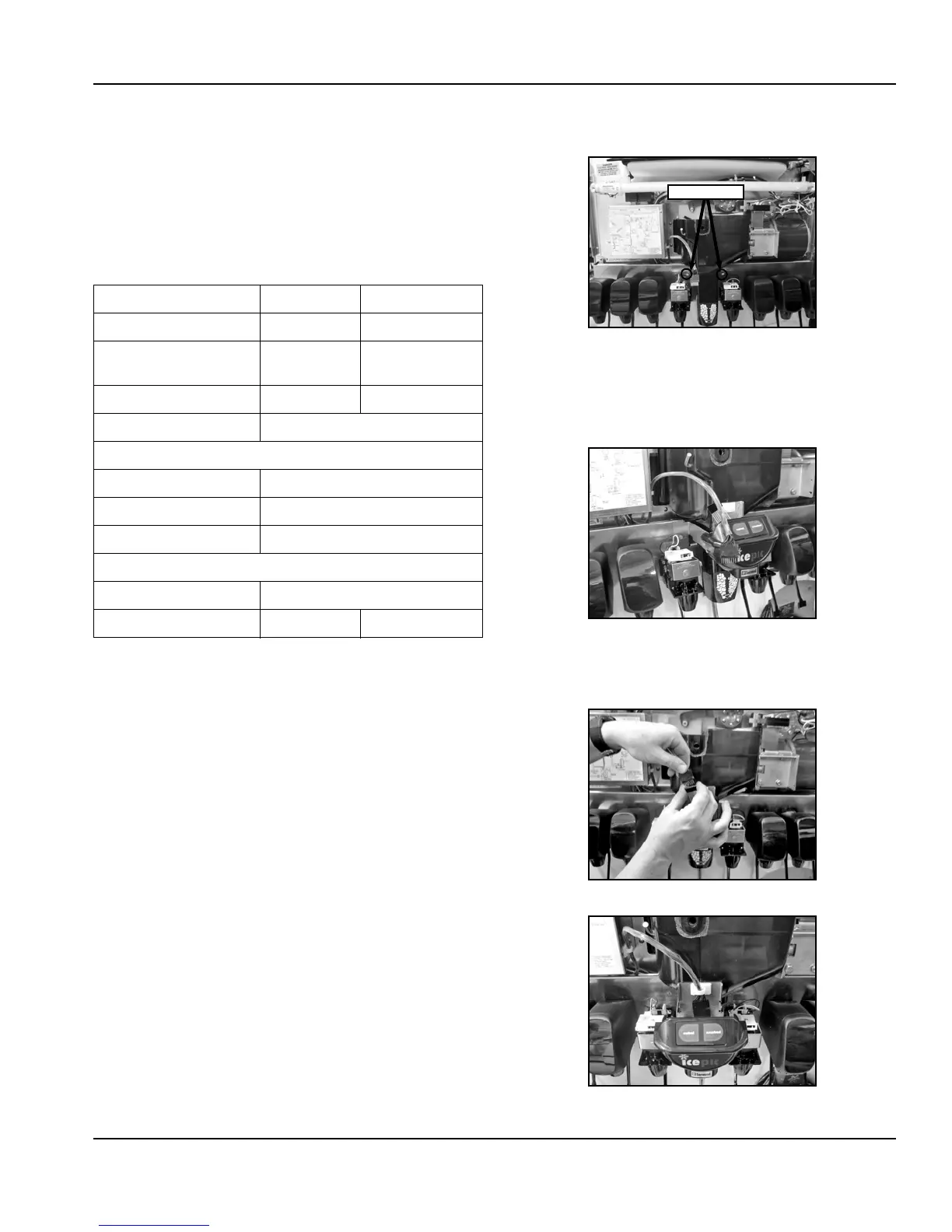
C. Remove the valve covers from the two valves next to the
rocking chute.
D. Loosen the two slotted knurl screws located on the valve
mount cap.
E. Hang the Selectable Ice Module bracket over the valve
mount cap, and secure to the valve mount cap by
tightening the knurl screws.
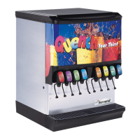
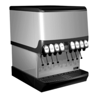
F. Connect the wiring harness to the Selectable Ice Module
(Figure 3) and locate the wire harness in the plastic clip as
seen in figure 4.
Min. Max
Water pressure 40 psi 55 psi
Ambient temperature 40°F
(4°C)
105°F
(41°C)
CO
2
pressure 40 psi 50 psi
Electrical 115V/60 Hz/1
Pre-mix pressure
Normal 60 psi*
Diet 40 psi*
B-I-B 60 psi or according to line run
Carbonation
Cold 75 psi
Ambient 90 psi 105 psi