01440D Light Industrial Gas Analyser Service Manual.2.4
6. The pipe from the outlet of the flow sensor, if fitted, goes to the upper
gas connector on the cell.
7. Ensure pipework is leak tight. See Section 2.13.1 or 2.13.2.
8. Calibrate the analyser and check both the analogue output and
display reading. See Section 2.5.
2.3.2 Replacement of the measuring Cell
1. Remove the Transducer as described in section 2.3.1.
2. Unsolder the yellow and black wires from the measuring cell and with
an Allen key loosen the cell locking clamp screw. Grip the cell by the
sides and pull the cell out of the magnet frame. (note that the magnet
will exert a very strong holding force on the cell)
3. The replacement cell must be fitted the correct way up with the yellow
spot connection at the top. With the cell fully home tighten the cell
locking clamp screw and re-solder the wires to the cell with the yellow
wire to the connection marked with the yellow spot.
4. Refit the transducer, using the ‘O’ rings supplied with the new cell, the
reverse of section 2.3.1, but do not refit the foam cover at this stage.
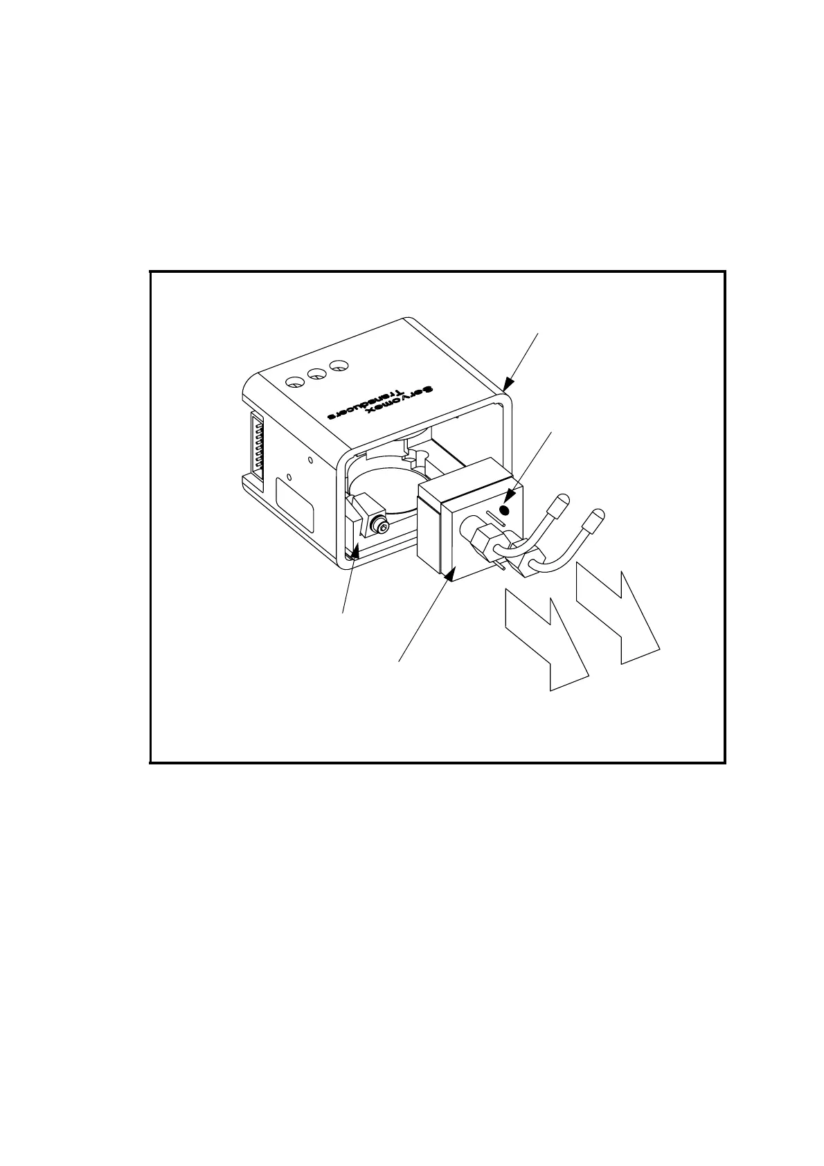
Figure 2.1 Cell Replacement
MAGNET FRAME
MEASURING CELL
LOCKING DEVICE
MEASURING CELL
YELLOW SPOT