01440D Light Industrial Gas Analyser Service Manual. 2.15
2.14.2 01440D1STD
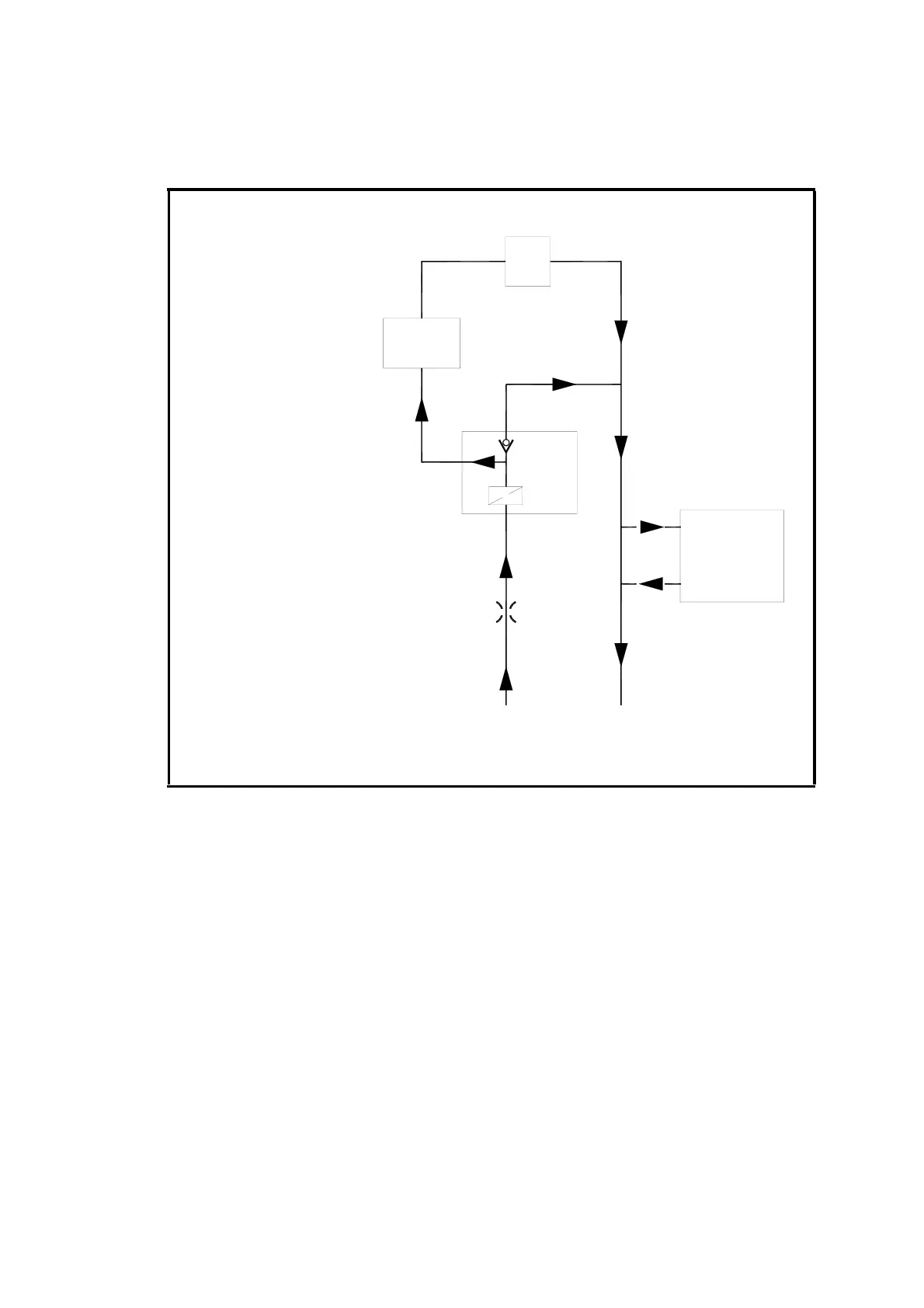
1. Follow the plumbing flow schematic shown in Figure 2.6.
2. Leak test by connecting together the sample 'IN' and sample 'OUT'
gas connections and connect a water manometer to them.
3. Pressurise the system to approx. 500mm water gauge and leave to
stabilise. The leak rate should be less than 2mm/min. after the level
has initially stabilised.
4. If a leak exists, check connections using a soap solution. This testing
should also include the oxygen cell and its window.
5. Rectify leaks and re-check.
Figure 2.6 01440D1STD Plumbing Schematic
CELL
FLOW
SENSOR
OUT
A.F.C.D
IN OUT
BACK
PRESSURE
REGULATOR
(OPTIONAL)
RESTRICTOR REQUIRED
FOR BACK PRESSURE
REGULATOR OPTION

 Loading...


