01440D Light Industrial Gas Analyser Service Manual. 2.11
2.8 Replacing the Relay/Output PCB (01420906)
1. Disconnect the flow sensor wires from TB4 and undo the four hexagonal fixing
sets located adjacent to the 15 way ‘D' connectors.
1. Disconnect the lower 34 way ribbon connector from the front panel PCB.
2. Disconnect the 16 way ribbon connector at the transducer.
3. The Relay/Output PCB may now be replaced, installation is the reverse of the
removal process, ensure all connections are remade (including the link across
TB4, 01440D1FTX only).
2.9 Replacing the Main Control PCB (01420915)
1. If necessary remove the transducer and power supply to improve access (See
Section 2.3.1 for oxygen transducer or 2.4.1 for infrared transducer).
2. Disconnect all connections to the display, noting their positions.
3. Undo the M3 screws and lift the PCB off of the three self-clinching spacers.
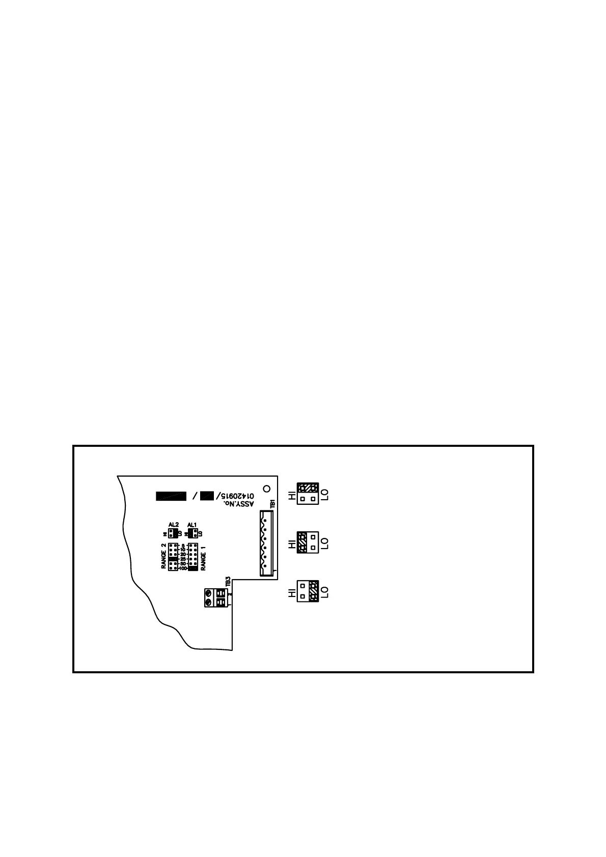
4. Fit new control PCB, TRANSFER LINK SETTINGS for ranges and alarms
(reference Figure 2.3).
5. Infra-red units only; it will be necessary to utilise links from the old PCB. Range
1 must be set to 100, range 2 must be linked across 10, 20 and 50).
6. Installation is the reverse of the removal process. Ensure spacers are
positioned correctly between boards.
Figure 2.3 Range Changes and Alarm Function Setting
ALARM ‘OFF’
ALARM ‘HI’
ALARM ‘LOW’