To fix automatism proceed as follows:
1- remove cover (Fig.6 part.B);
2- disconnect all wiring (encoder, switches, transformer, motor) on control board;
3- unscrew the 2 screws (Fig.6 part.C) and remove control board with its support (screws remain between control board and
support);
4- unscrew the 2 screws (Fig.6 part.G) and remove transform;
5- unscrew the 4 screws (Fig.6 part.E) and remove gear motor;
6- unscrew screws (Fig.6 part.I)and remove end caps (Fig.6 part.M ed L);
7- fix aluminium base (Fig.6 part.N) to thre structure following instructions of the following paragraphs, dipending on arm type;
8- reassemble all components but end caps and aluminium cover.
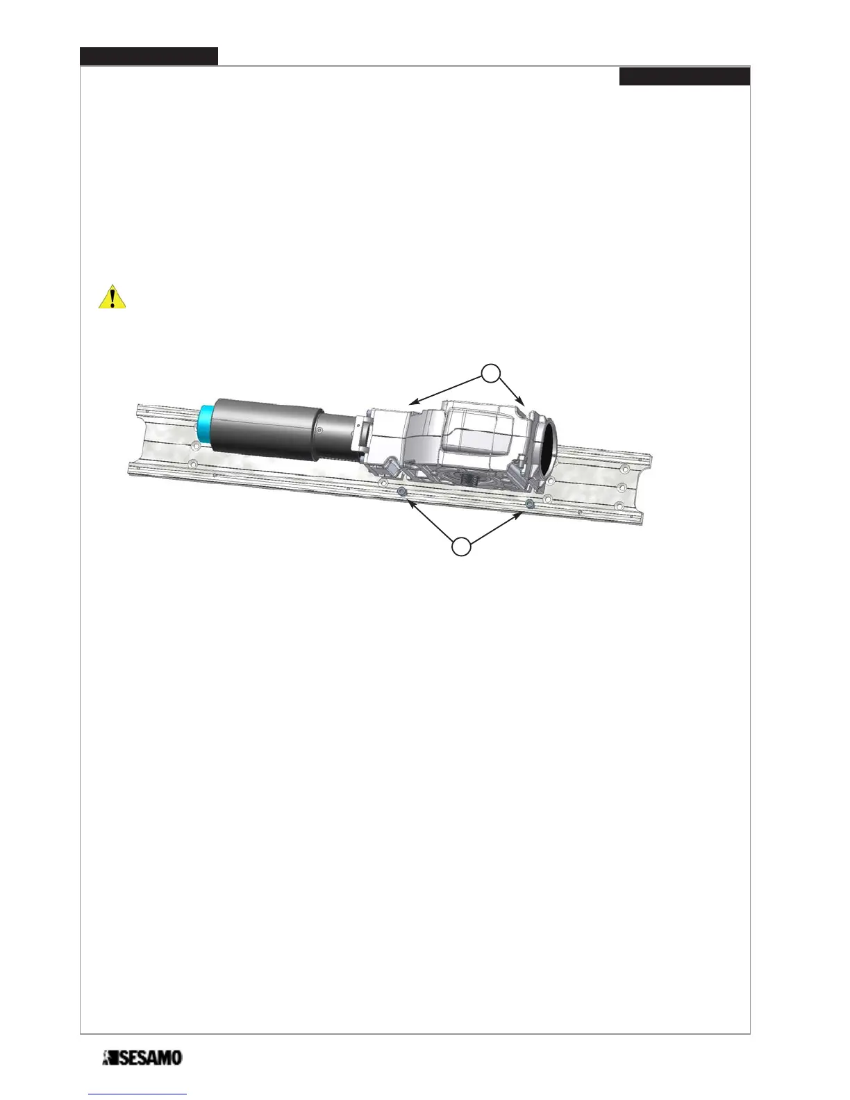
ATTENTION: to make easier reassembling gear motor, partially screw the screws (Fig. 7 part. E), then lean gear motor
on to them. Insert screws (Fig. 7 part. F).
Tight all screws paying attention that gear motor axis is perpendicular to the door top edge.
Fig. 7
E
F
PROSWING (M)
Operating instruction
12