Setra FLEX Operating Instructions
10
Phone: (800) 257-3872 | Fax: (978) 264-0292 | www.setra.com
2.4 Installation Overview
EachFLEXunitcomescompleteperorderspecications
to provide a full room environment monitoring solution
for pressure, temperature, relative humidity, air change
rate,andtwouser-denedparameters.Supportforupto
3 rooms is included with each FLEX product. Installation
proceeds via the steps noted below, with variations
dependingonorderconguration.
1. Install 3-gang electrical box for FLEX main unit. Box
depth requirement varies depending on whether an on-
board sensor is factory-installed.
2. Install 1-gang electrical box for each Pressure Pickup
Port, either horizontal ceiling-mounted or vertically
mounted high on a wall surface.
3. Ensureelectricalboxesarelevelandflushtothenished
wall surface.
Note: Surface mount adapter boxes are available for
installation where cutting into the wall is not possible
(Setra P/N 229973 for FLEX units without on-board
pressure sensor; Setra P/N 229971 for FLEX units with
on-board pressure sensor).
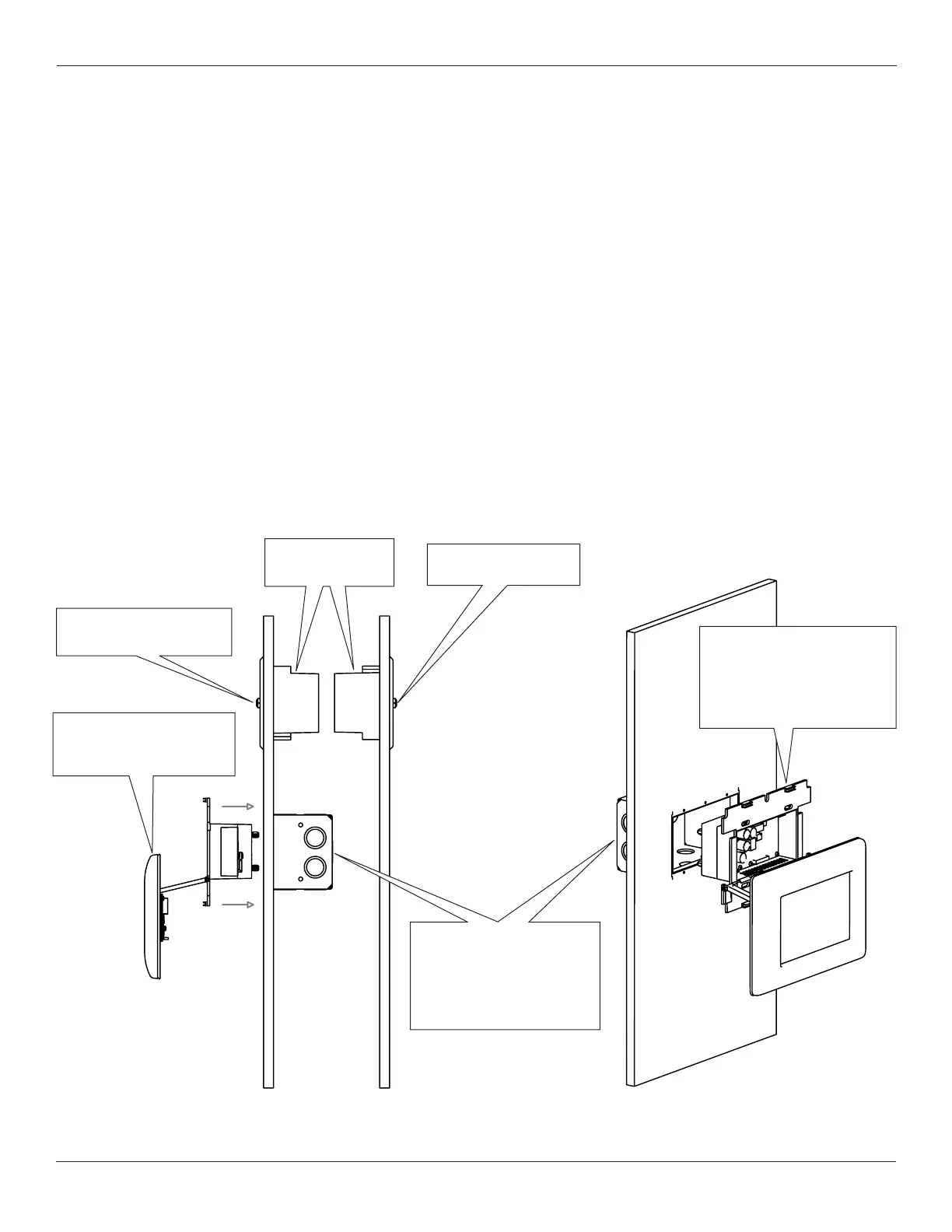
1-Gang
Electric Box
Setra RPS
Reference Pressure Side
Setra RPS
Room Pressure Side
Setra FLEX Unit
(may be mounted inside
or outside room)
Wall Cavity
Electrical Box
(3-Gang double-deep if
using on-board sensor,
single deep if no
on-board sensor)
Setra FLEX Unit
(Display hinges down
during installation then
snaps in place when
mounting is complete)
With On-board Pressure Sensing
• Install room-side and reference-side Pressure Pickup
Ports, which sense and transmit pressure measurement
to the FLEX unit.
• Run tubing to FLEX electrical box, being careful not to
crimp tubing in conduit or within walls.
• Run all wiring and network connections to the FLEX
electrical box
With External Pressure Sensing
• Install room-side and reference-side Pressure Pickup
Ports, which sense and transmit pressure measurement
to the FLEX unit.
• Mount external transducers (Setra model 264 or 267) in
a NEMA enclosure or other suitable location that enables
convenient access for commissioning and servicing.
• Run tubing to external transducers, being careful not to
crimp tubing anywhere across the run.
• Run external transducer output signal wires, remaining
wiring and network connection to the FLEX electrical box.