Setra FLEX Operating Instructions
12
Phone: (800) 257-3872 | Fax: (978) 264-0292 | www.setra.com
Considerations to Avoid Kinked or Damaged Tubing
Pull tubing runs in a manner that protects the tubing from
being damaged, cut, or crimped. Any break or bend in the
tubing may affect the integrity of the pressure signal. DO
NOT TIGHTEN STRAIN RELIEFS at the electrical boxes so
that they crimp the tubing. Leave the strain reliefs open
enough so that the tubing can slide in and out of the
box with a few inches of play. Prior to use, tape the open
ends of the tubes closed to prevent contamination during
construction.
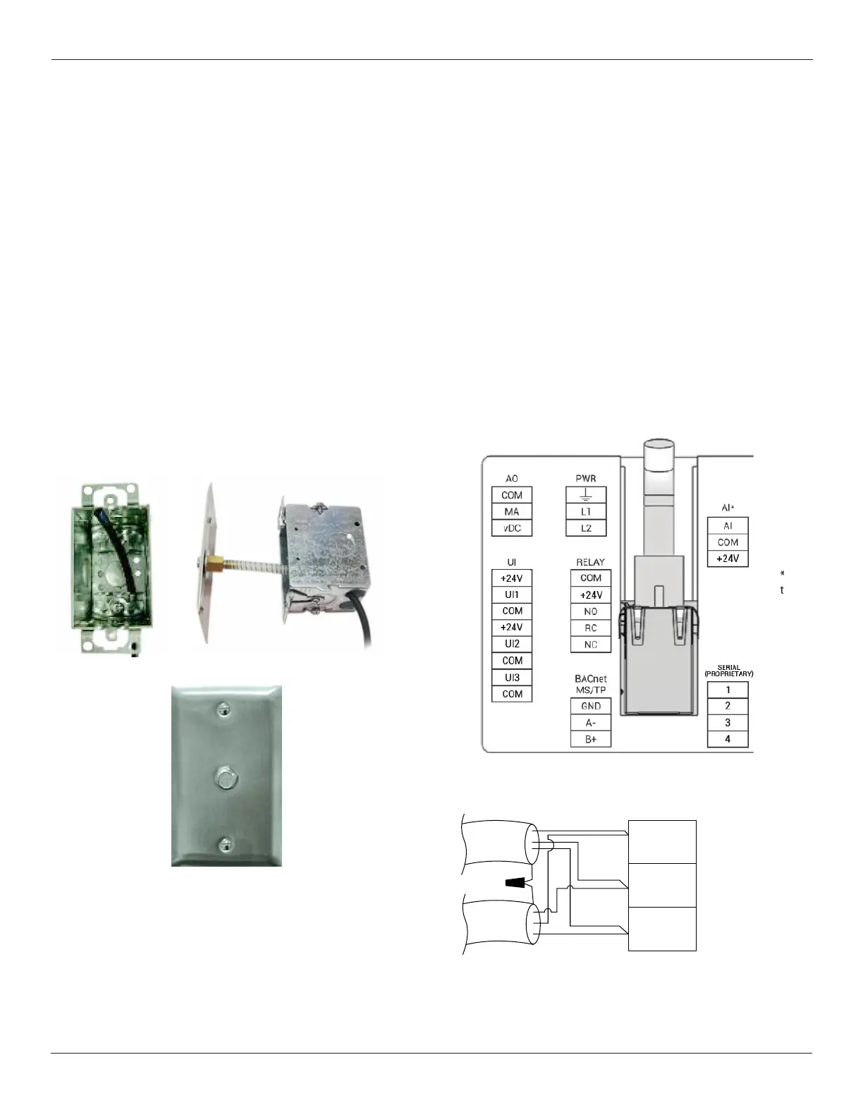
DuringnalinstallationofthePressurePickupPorts,use
the included clear spring-wound adapters between the
nylon wall tubing and the back of the Pressure Pickup
Port, (as shown below). This will ensure when the port is
mounted to the wall that the tubing assembly does not
crimp inside the electrical box. Careful observation should
be made of how the tubing gets pushed back into the wall
fornalfaceplatemounting.
In a similar manner, mount remaining Pressure Pickup
Ports and the FLEX unit if using an on-board sensor.
Use of External Pressure Sensors
If FLEX is being used exclusively with external pressure
sensors, or in combination with an on-board sensor, the
external sensors require no tubing runs to the FLEX unit
itself. Instead, the external sensors will be separately
mounted, plumbed and wired. Only the wire for the analog
output of that sensor(s) will be run to the FLEX unit.
Wiring the FLEX Main Unit
The back of the FLEX unit has terminal blocks labeled
with their function. Universal inputs, marked “UI” will be
conguredforeitherAnalogInputsorDigitalInputsinthe
FLEXcongurationsetup.
Power
The 3-pin power connection for FLEX is labeled “PWR” on
the rear of the unit.
1. Pull off the removable PWR terminal block
2. Connect the 24 VAC lines to L1 and L2
3. Connect a ground wire to the ground terminal (if
provided)
4. Push the removable terminal block back into the PWR
connection
FLEX operates at 18-30 VAC, 50/60 Hz, and consumes 10
W nominal, 13 W maximum.
BACnet MS/TP Detail
*AI for on-board
transducer or
general AI input
B (+)
A (-)
GND
DATA +
DATA -