3
Configuration
24V supply voltage selection
Product Manual – MOVIDRIVE
®
modular
177
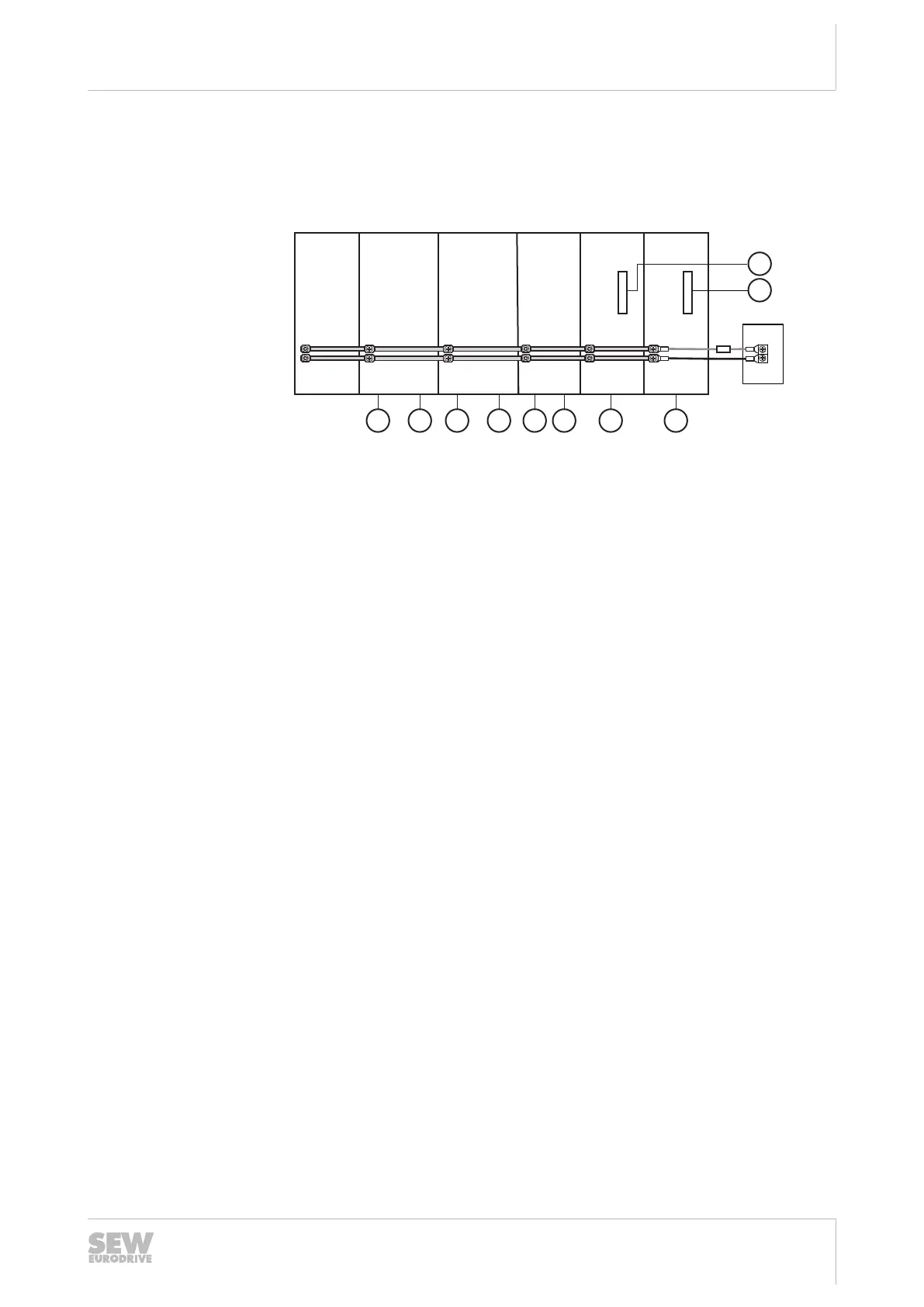
3.13.7 Project planning example
The following example shows the configuration of the 24V voltage supply of an axis
system.
24V
24V
24V
24V
24V
24V
24V
24V
+
–
+
-
MDP 10 kW MDD 8 A MDD 8 A MDD 4 A MDA 4 A MDA 2 A
M1 M2 M3 M4 M5 M6 M7 M8
G1
G2
[1]
[2]
18014417353521291
[1] 24V voltage supply [2] DC 24 V fuse
Modules and devices used in the axis system:
• 8 brakemotors – 4 × CMP63S with BK03, 4 × CMP50M with BK02
• 8 motor encoders in the basic device
• 2 external encoders with CES11A option
• 8 × 4 digital outputs in the axis modules
• MDP power supply module 10kW
• 2 MDD double-axis modules 8A
• 1 MDD double-axis module 4A
• 1 MDA single-axis module 4A
• 1 MDA single-axis module 2 A
The total power consumption is calculated from the total power consumption of all
used modules, cards, and externally connected devices.
• 4 × brake BK03: 4 × 14 W = 56 W
• 4 × brake BK02: 4 × 7 W = 28 W
• 8 × motor encoder: 8 × 5 W = 40 W
• 2 × external encoder: 2 × 12 W = 24 W
• 2 × CES11A card: 2 × 0.8W = 1.6W
• 8 × 4 digital outputs in the axis modules 8×4×1.2W=38.4W
• 1 MDP power supply module 10kW: 15W
• 2 MDD double-axis modules 8A: 2 × 22 W = 44 W
• 1 MDD double-axis module 4 A: 20 W
• 1 MDA single-axis module 4A: 20 W
• 1 MDA single-axis module 2 A: 20 W
The external 24V supply must be selected to ensure that the sum of the individual
power levels is 307W, and the resulting current is 12.8A.
Check of one or two-sided supply: 12.8 A < 40A →one-sided supply.
25952676/EN – 01/2020
 Loading...