7
Device structure, axis system structure
Device structure of the MDP power supply module
Product Manual – MOVIDRIVE
®
modular
255
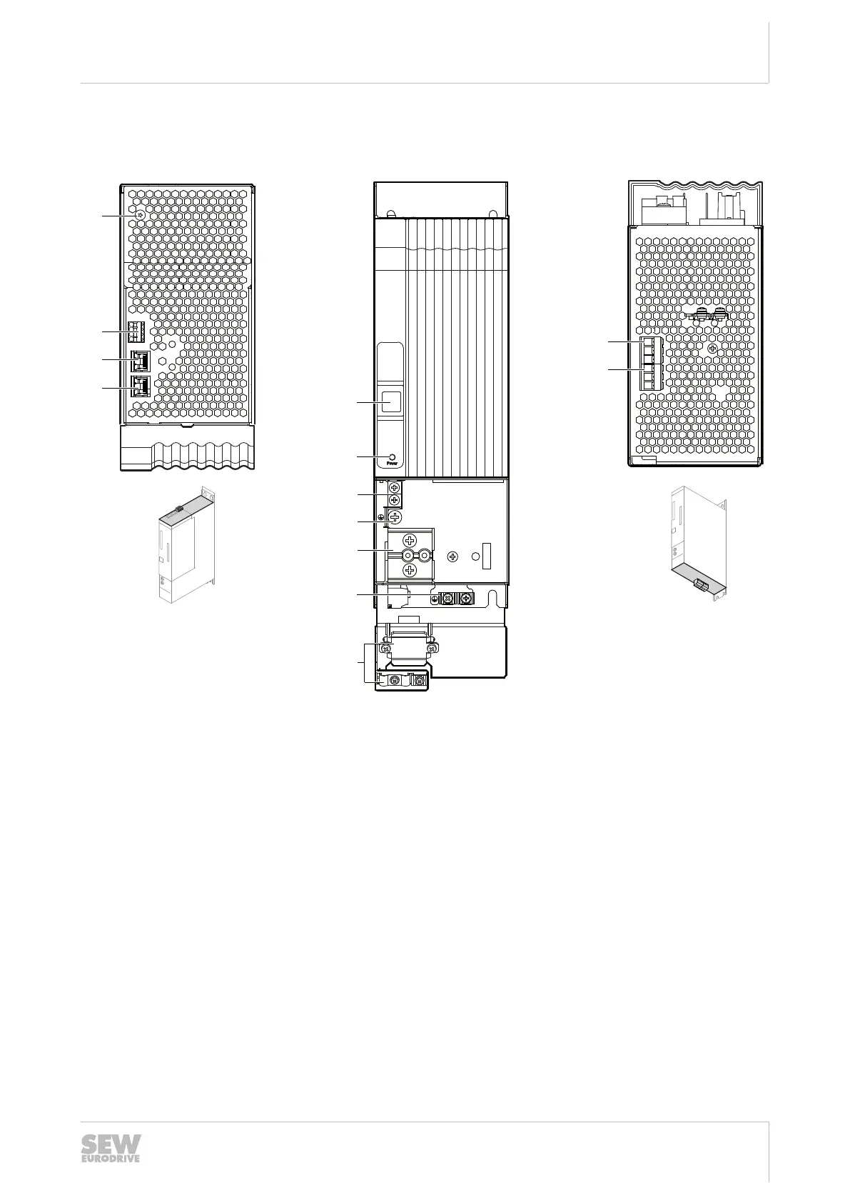
7.4.2 MDP90A-0100-.. with integrated braking resistance (size 1A)
X1 X3
24V
X5
+UZ
X4
-UZ
-UZ +UZ
GND
X7
X30 OUTX30 IN
A B C
[2]
[3]
[4]
[1]
[7]
[8]
[9]
[5]
[6]
[10]
[12]
[13]
[11]
1
2
3
4
18014411422566667
A: View from top B: View from front C: View from bottom
[1] Terminal screw for TN/TT sys-
tems
[5] 7-segment display [12] X3: Braking resistor con-
nection
[2] X7: Braking resistor temperature
monitoring
[6] Power: LED display DC link
voltage
[13] X1: Line connection
[3] X30 OUT: System bus [7] X5: Connection +24V supply
voltage
[4] X30 IN: System bus [8] PE connection
[9] X4: DC link busbar
[10] PE connection housing
[11] Shield terminal
25952676/EN – 01/2020
 Loading...