7
Device structure, axis system structure
Device structure of the MDP power supply module
Product Manual – MOVIDRIVE
®
modular
254
7.4 Device structure of the MDP power supply module
WARNING
Uncovered power connections.
Some of the modules shown in this chapter are depicted without touch guards.
Touch guards secure the live parts such as DC link, line connections and braking re-
sistor connections.
Severe or fatal injuries from electric shock
• Never start up the application inverter without installed closed touch guards.
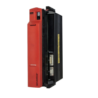
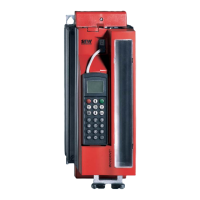
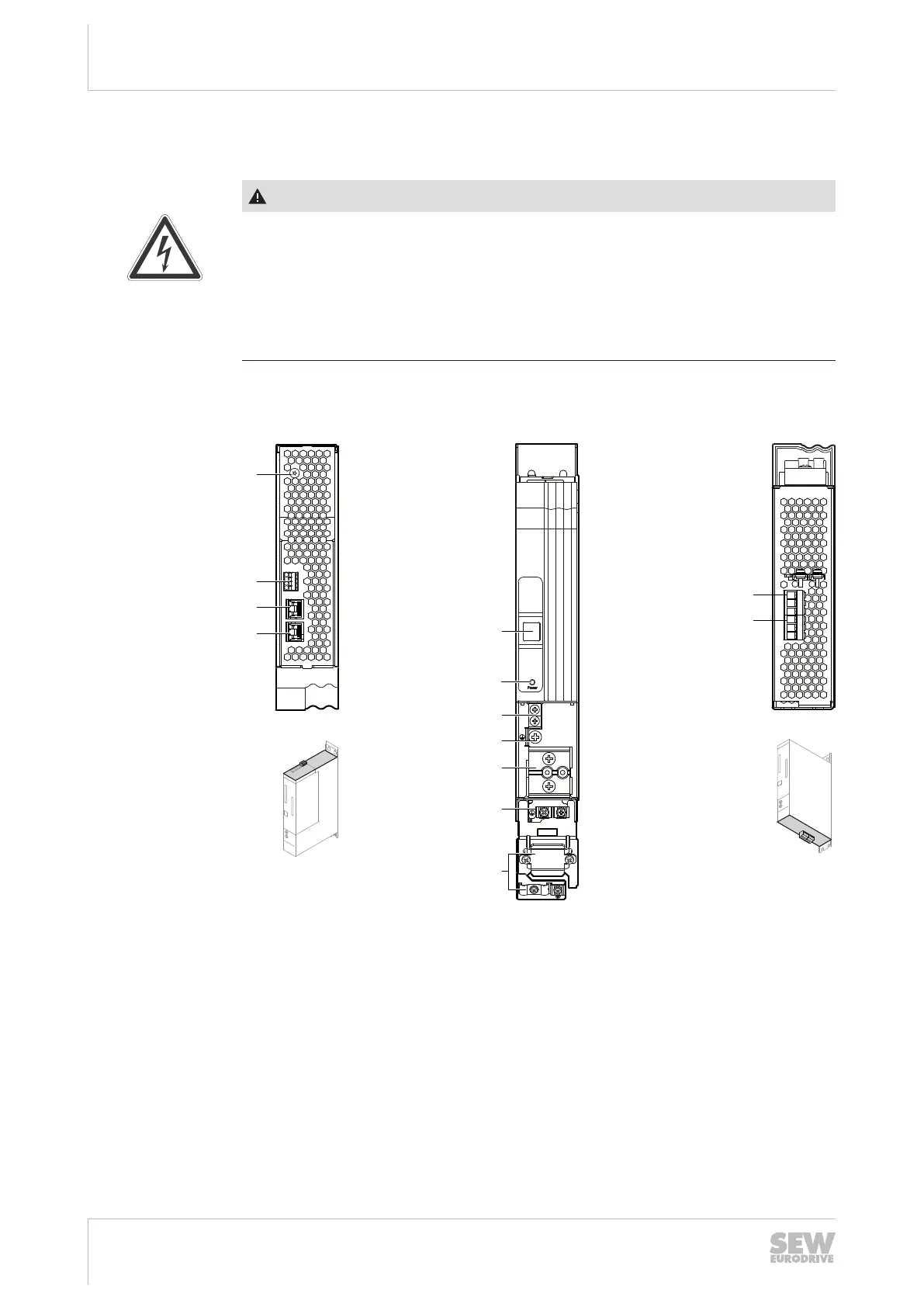
7.4.1 MDP90A-0100-.. (size 1)
24V
X5
+UZ
X4
-UZ
-UZ +UZ
GND
X7
X30 OUTX30 IN
BA C
[7]
[8]
[9]
[12]
[13]
[2]
[3]
[4]
[5]
[6]
[10]
[1]
X1 X3
[11]
1
2
3
4
18014411422564235
A: View from top B: View from front C: View from bottom
[1] Terminal screw for TN/
TT systems
[5] 7-segment display [12] X3: Braking resistor
connection
[2] X7: Braking resistor
temperature monitor-
ing
[6] Power: LED display DC link
voltage
[13] X1: Line connection
[3] X30 OUT: System bus [7] X5: Connection +24V sup-
ply voltage
[4] X30 IN: System bus [8] PE connection
[9] X4: DC link busbar
[10] PE connection housing
[11] Shield terminal
25952676/EN – 01/2020
 Loading...