10
Project planning
MOVIGEAR® performance
Operating Instructions – MOVIGEAR
®
performance
303
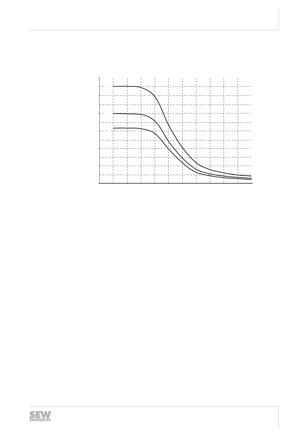
10.3.3 Regenerative load capacity of the integrated braking resistor
The following diagram shows the load capacity per braking operation of the BW1 brak-
ing resistor integrated in MOVIGEAR
®
as standard:
200
300
400
500
600
[J]
[1]
[2]
[3]
0
100
01050 100 200 500 1000 2000 3000 4000 5000 6000
[c/h]
25291390987
[1] Brake ramp 10s
[2] Brake ramp 4s
[3] Brake ramp 0.2s
c/h Cycles/hour
Calculation example
The known values are:
• Average braking power: 11.8W
• Deceleration ramp: 0.92s
• 6 brake applications per hour
Calculating the energy from the power of the deceleration ramp:
W P t W s J= × = × =11 8 0 92 10 9. . .
The specified deceleration ramp in seconds refers to a speed change of 3000min
−1
.
Calculation of the deceleration ramp for MOVIGEAR
®
: a
down
= 3000min
−1
x 0.92s /
1863min
−1
= 1.5s.
For the deceleration ramp of 1.5s, you can use deceleration ramp [3] (0.2s) in the
diagram. Use the characteristic curve with the shorter deceleration ramp because a
shorter deceleration ramp means more braking energy.
The diagram permits 310 J of braking energy for the 0.2 s deceleration ramp at
6cycles per hour. In this case, the required 10.9J can be dissipated via BW1.
25945475/EN – 04/2019

 Loading...