4
Installation
Electrical installation
Operating Instructions – MOVITRAC
®
LTP-B
47
4.4.16 24V backup mode
24 V backup mode is not necessary for simple operation. Wiring is therefore not ne-
cessary. In order to ensure fieldbus communication via a fieldbus interface in the
event of a power failure, back up the inverter externally with 24V.
Requirements
Firmware version 1.20 (can be seen in P0-28).
Range of functions
• Parameter access (reading only, no writing)
• Fieldbus communication
Setting up 24V backup mode
All inverters that are connected to each other in a communication network and use the
24V backup mode have to be supplied simultaneously with external 24V. Make sure
that individual devices that are connected in the network are not separated from 24V.
INFORMATION
Errors in the fieldbus network may occur if the inverters are not supplied by the power
supply and individual devices that are in the RJ45 network or the optional fieldbus
network are separated from the external 24V supply. Make sure that all connected
inverters are always supplied with external 24V at the same time.
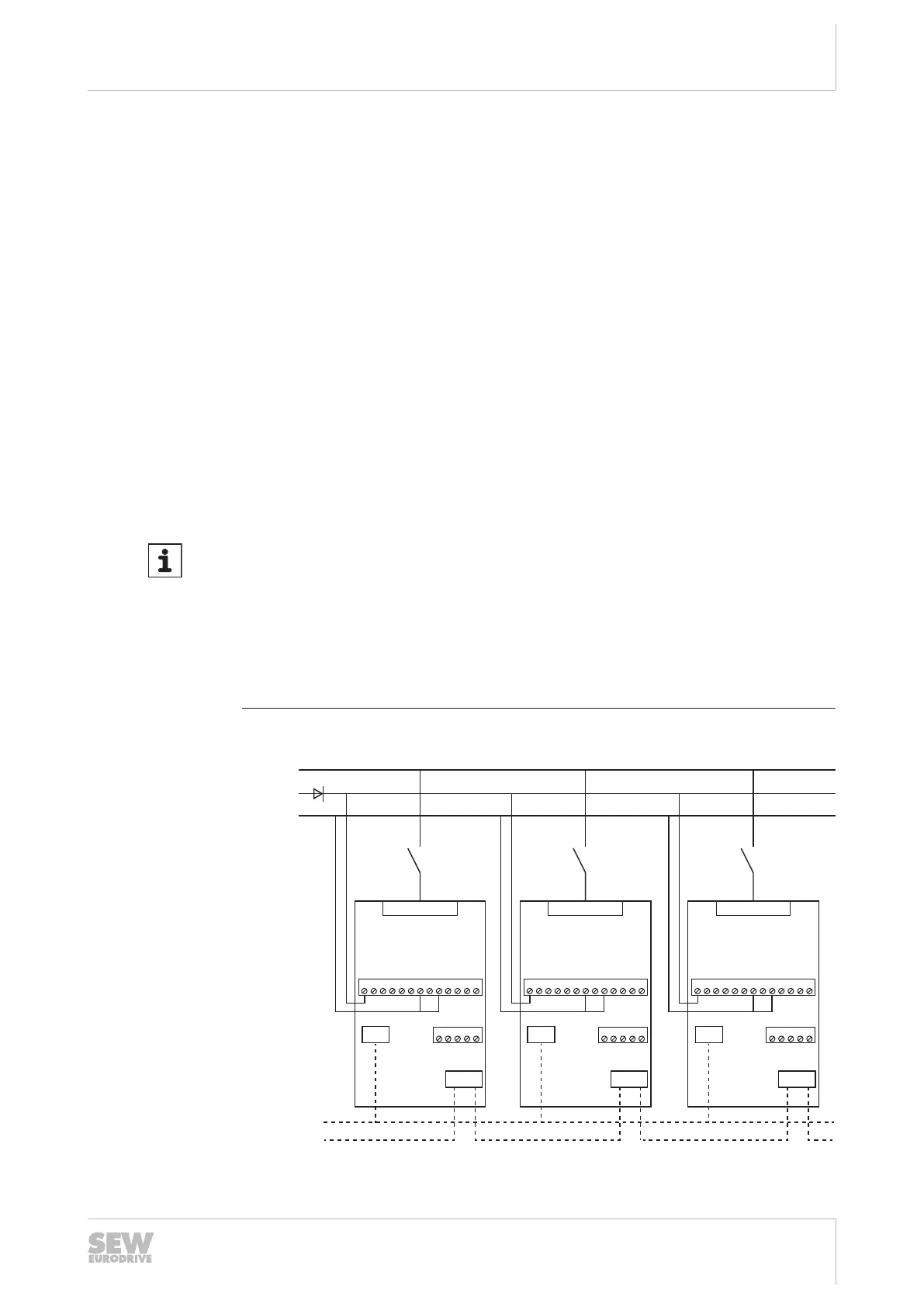
The 24 V supply to the inverters must come via a diode terminal since the inverters
could also supply other devices with 24V, which can subsequently cause an over-
load of the internal switched-mode power supply and, under certain circumstances,
cause damage as well.
Example of a wiring diagram
Grid
Grid
24 V
0 V/GND
Communication
via RJ45 or
optional
fieldbus interface
+24 VIO
DI 1
DI 2
DI 3
+10 V
AI 1 / DI 4
AI 2 / DI 5
AO 1 / DC
AO 2 / DC
STO+
STO-
0 V
0 V
1 2
RJ45
Relays
Option
3 4 5 6 7 8 9 10 111213
14 151617 18
Grid
+24 VIO
DI 1
DI 2
DI 3
+10 V
AI 1 / DI 4
AI 2 / DI 5
AO 1 / DC
AO 2 / DC
STO+
STO-
0 V
0 V
1 2
RJ45
Relays
Option
3 4 5 6 7 8 9 10 111213
14 151617 18
Grid
+24 VIO
DI 1
DI 2
DI 3
+10 V
AI 1 / DI 4
AI 2 / DI 5
AO 1 / DC
AO 2 / DC
STO+
STO-
0 V
0 V
1 2
RJ45
Relays
Option
3 4 5 6 7 8 9 10 111213
14 151617 18
9007217619287307
25813137/EN – 08/2018

 Loading...