AR-M256/M257/M258/M316/M317/M318/5625/5631 SIMULATION 8 - 13
Operation/procedure
1. Touch the exposure mode to be changed.
The current set value is displayed.
2. Enter the set value with the 10-key.
3. Press the [START] key.
Output is made with the entered value for 30sec, and the display
returns to the original state.
Min. unit: –25V increment
(
∗) Linked with the destinations of SIM 26-6.
Linked with the auto exposure mode of SIM 46-19-1.
*1. The negative value of the set value corresponds to the grid high
output voltage.
*2. The set values can be selected from the above 10 patterns only.
*3. The selected pattern determines the grid high voltage and the grid
low voltage.
If, for example, the grid high voltage is set to –555V (pattern 1), the
grid low voltage is –455V.
Operation/procedure
1. Touch the exposure mode to be changed.
The current set value is highlighted.
2. Enter the set value with the 10-key.
3. Press the [START] key.
Output is made with the entered value for 30sec, and the display
returns to the original state.
Min. unit: –25V increment
(
∗) Linked with the destinations of SIM 26-6.
Linked with the auto exposure mode of SIM 46-19-1.
*1. The negative value of the set value corresponds to the grid high
output voltage.
*2. The set values can be selected from the above 10 patterns only.
*3. The selected pattern determines the grid high voltage and the grid
low voltage.
If, for example, the grid high voltage is set to –555V (pattern 1), the
grid low voltage is –455V.
8-2
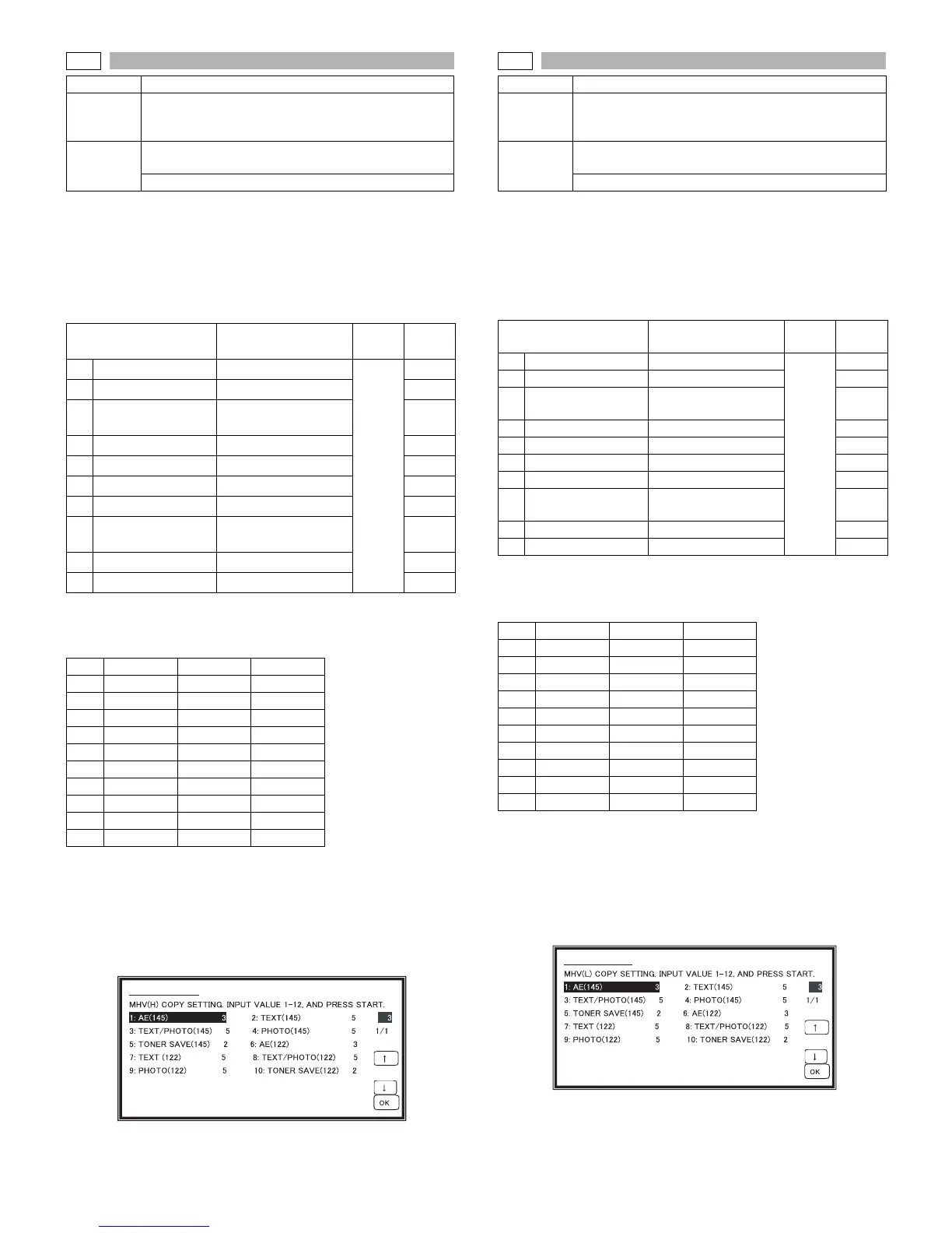
Purpose Adjustment/Operation test/check
Function
(Purpose)
Used to check and adjust the operation of the main
charger grid voltage (high mode) in each copy mode
and the control circuit.
Section
Image process
(Photoconductor/Developing/Transfer/Cleaning)
Photo conductor
Item Content
Setting
range
Default
1 AE (145) AE (145mm/s)
1-12
4
2 TEXT (145) Character (145mm/s) 6
3 TEXT/PHOTO (145)
Character/Photo
(145mm/s)
6
4 PHOTO (145) Photo (145mm/s) 6
5 TONER SAVE (145) Toner save (145mm/s) 2
6 AE (122) AE (122mm/s) 3
7 TEXT (122) Character (122mm/s) 5
8 TEXT/PHOTO (122)
Character/Photo
(122mm/s)
5
9 PHOTO (122) Photo (122mm/s) 5
10 TONER SAVE (122) Toner save (122mm/s) 2
NO. Set value Grid High Grid Low
1 4 –555V –455V
2 6 –605V –505V
3 6 –605V –505V
4 6 –605V –505V
5 2 –505V –405V
6 3 –530V –405V
7 5 –580V –455V
8 5 –580V –455V
9 5 –580V –455V
10 2 –505V –380V
SIMULATION 8-2
8-3
Purpose Adjustment/Operation test/check
Function
(Purpose)
Used to check and adjust the operation of the main
charger grid voltage (low mode) in each copy mode
and the control circuit.
Section
Image process
(Photoconductor/Developing/Transfer/Cleaning)
Photo conductor
Item Content
Setting
range
Default
1 AE (145) AE (145mm/s)
1-12
4
2 TEXT (145) Character (145mm/s) 6
3 TEXT/PHOTO (145)
Character/Photo
(145mm/s)
6
4 PHOTO (145) Photo (145mm/s) 6
5 TONER SAVE (145) Toner save (145mm/s) 2
6 AE (122) AE (122mm/s) 3
7 TEXT (122) Character (122mm/s) 5
8 TEXT/PHOTO (122)
Character/Photo
(122mm/s)
5
9 PHOTO (122) Photo (122mm/s) 5
10 TONER SAVE (122) Toner save (122mm/s) 2
NO. Set value Grid High Grid Low
1 4 –555V –455V
2 6 –605V –505V
3 6 –605V –505V
4 6 –605V –505V
5 2 –505V –405V
6 3 –530V –405V
7 5 –580V –455V
8 5 –580V –455V
9 5 –580V –455V
10 2 –505V –380V
SIMULATION 8-3