9.
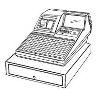
Replace the top cabinet and drawer.
(Refer to Section 5
“REMOVINGTHE TOP CABINET AND MAIN DRAWER”.) At this time draw
out the drawer cable from the bottom cabinet at the back or
through cable hole @ on its right side (see Fig. 16 on page
49).
Use care to prevent the drawer cable, groundingwire, etc.
from being caught between the bottom cabinet and the drawer.
6.3 Operationalcheck
0 Preparation
Connect the test connector to the 25-pin RS-232C connector (25P
D-sub) of the ER-31Rs2.
QCNW-7059RCZZ
ER-31RS2
/
Testconnector
$ 0
UKOG-6639RCZZ
MainPWB
Interface
PWB
CPWBF6951RC06
After connectingthe test connector (UKOG-6639RCZZ)to the 25P
D-sub, interfacePWB input and output signalsmust be connected
in followingmanner.
,
I
ER
DR
0 Start of the test
The test will start after the followingkeyboard command in the
SRV mode.
119~
n
Note:
The above command would not be acceptedunless the
ER-31RS2 control ROM (27256)is in the ROM socket (ROM3)
on the main PWB of the ER-31OO.
The above operationwill
cause the “Check over”
print and automaticallyfinalize
the check program.
–20–