LC-40/46/52/60LE810UN (1st Edition)
5 – 9
7. Microcomputer software writing
7.1. Main microcomputer/monitor microcomputer software writing (Main PWB: QPWBXF452WJZZ)
7.2. Model/inch discrimination writing (Main PWB: QPWBXF452WJZZ)
• Refer to the production precautions.
8. Signal adjustment
8.1. LCD section adjustment [LCD module adjustment]
8.2. Image adjustment
8.2.1 Device check
Before adjustment, check that the adjustment jig and signal source are set for Sharp LCD US.
Signal generator level adjustment check (Adjust to the standard value level.)
8.2.2 Process mode
Adjustment item Adjustment conditions Adjustment procedure
1 Main microcomputer/moni-
tor microcomputer software
writing
<Main PWB>
Checker process
File version check
USB memory check
1. Connect the specified writing jig to SC8452 (TL8461-8475) via the checker.
2. Connect the USB memory to J3301 (TL3309-3312) or J3302 (TL3332-3335)
via the checker.
3. Apply the specified voltage to the PWB and perform boot from the jig.
4. Send the software writing start command via RS232C.
5. Send the writing status check command and confirm the response of OK. Then
turn off the power.
CAUTION: When the USB memory is not inserted or reading error occurs, nothing
is written.
Adjustment item Adjustment conditions Adjustment procedure
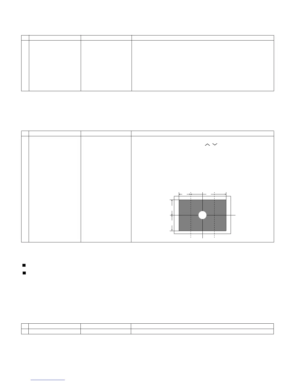
1 Opposite bias adjustment
(LCD module adjustment
item)
Adjustment in the center
position of the panel
1. Enter the process mode using the process adjustment remote control.
2. Select [VCOM ADJ] using the Channel / keys on the remote control.
3. Press the Enter key to check that the pattern for adjustment is displayed.
4. Make adjustment so that the flicker located in the center of the screen is mini-
mized using the Volume +/- keys on the remote control.
5. If the optimum condition is obtained in step 4, press the Enter key to turn off the
pattern.
CAUTION: * Make adjustment with no ANT signal (since the brightness is
changed by the active backlight).
[Adjustment position]
•Composite signal: 0.714Vp-p ± 0.02Vp-p (Pedestal to white)
•15K component signal: Y level: 0.714Vp-p± 0.02Vp-p (Pedestal to white)
PB/PR level: 0.7Vp-p ± 0.02Vp-p
•33K component signal: Y level: 0.7Vp-p ± 0.02Vp-p (Pedestal to white)
PB/PR level: 0.7Vp-p ± 0.02Vp-p
•Analog RGB: RGB level: 0.7Vp-p ± 0.02Vp-p (Pedestal to white)
Adjustment point Adjustment conditions Adjustment procedure
Process mode Enter the process adjustment mode using the process adjustment remote control.