Note: When the lens drive wire is removed, the magnification adjust-
ment and the focus adjustment are required.
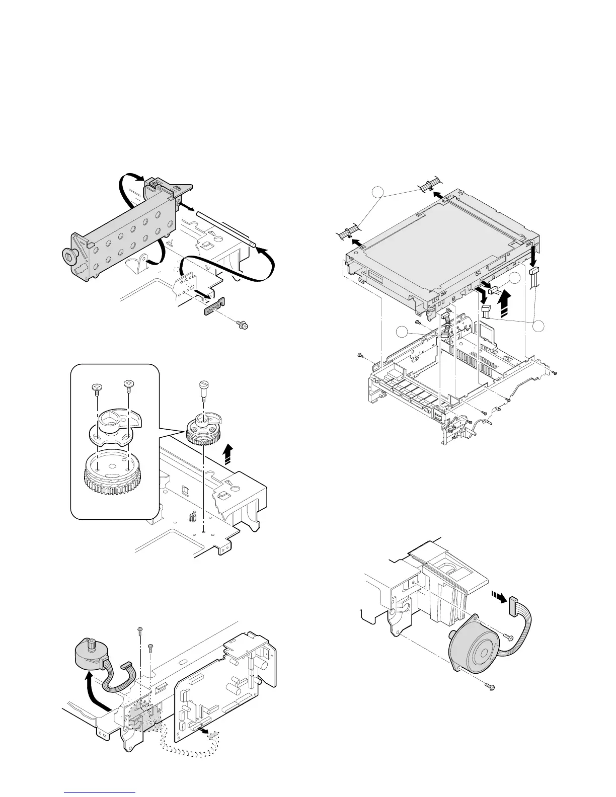
4-5. No. 4/5 mirror unit and peripheral parts
replacement
1 Remove the manual paper fed unit, the right upper cabinet, and
the table glass.
2 Remove the dark box cover fixing screw (1 pc.) and remove the
cover.
3 Remove the mirror holder spring.
4 Remove the shaft mounting plate, pull out the shaft towards the
paper feed side, and remove No. 4/5 mirror unit.
5 Remove the fixing screw of the center section of the drive pulley,
and remove the pulley.
6 Remove the CN-E connector of the main PWB, remove the drive
motor fixing screws (2 pcs.), and remove the No.4/5 mirror unit
from the mounting section (square hole in the base plate).
For assembly, reverse the disassembly procedures.
4-6. Optical unit removal
1 Remove the drum unit and the developer unit.
2 Remove the right cabinet, the left cabinet, the operation panel, the
medium cabinet, and the rear cabinet.
3 Remove three connectors A from the sensors in the rear as
shown in the figure.
4 Remove connector B between the mirror motor and the main
PWB (CN-C).
5 Remove two snap bands C which are binding cables of the
operation panel.
6 Remove the optical unit .
4-7. Other parts in the optical system
1 Remove the rear upper cabinet.
2 Remove the CN-C connector of the main PWB and the fixing
screws (2 pcs.), and pull out the mirror motor towards the rear
frame.
C
A
A
B
6 – 11