VII. Troubles caused by improper adjustment
(2) Mirror
There are following adjustments of parts installation positions related
to the mirror.
*
No. 4/5 mirror unit right angle adjustment
*
No. 4/5 mirror unit drive cam position adjustment
a. No. 4/5 mirror unit right angle adjustment
I. Summary
Copy image distortion caused by No. 4/5 mirror unit van be
reduced by setting the optical axis of the copier and No. 4/5
mirror unit.
The horizontal angle of the lens unit slide shaft is adjusted by
changing the position of No. 4/5 mirror nit slide shaft fixing plate.
This adjustment is performed not by checking a copy image but
by visual measurement with the optical unit base plate as the
reference.
Copy image distortion must be adjusted ont only in this adjust-
ment but also in the No. 1/2 scanner unit parallelism adjustment.
II. Purpose
The purpose of this adjustment is to eliminate copy image distor-
tion by setting the optical axis of the copier and that of the No.
4/5 mirror unit in parallel with each other.
III. Note
The copy image distortion adjustment is completed by making a
copy and adjusting the parallelism of No. 1 and No. 2 scanner
units.
For that purpose, this adjustment must have been properly per-
formed.
IV. Cases when the adjustment is required
1) When No. 4/5 mirror unit is disassembled or its part is
replaced.
2) When the copy image is distorted as follows:
V. Necessary tools:
*
Screwdriver (+)
*
Scale
VI. Adjustment procedure
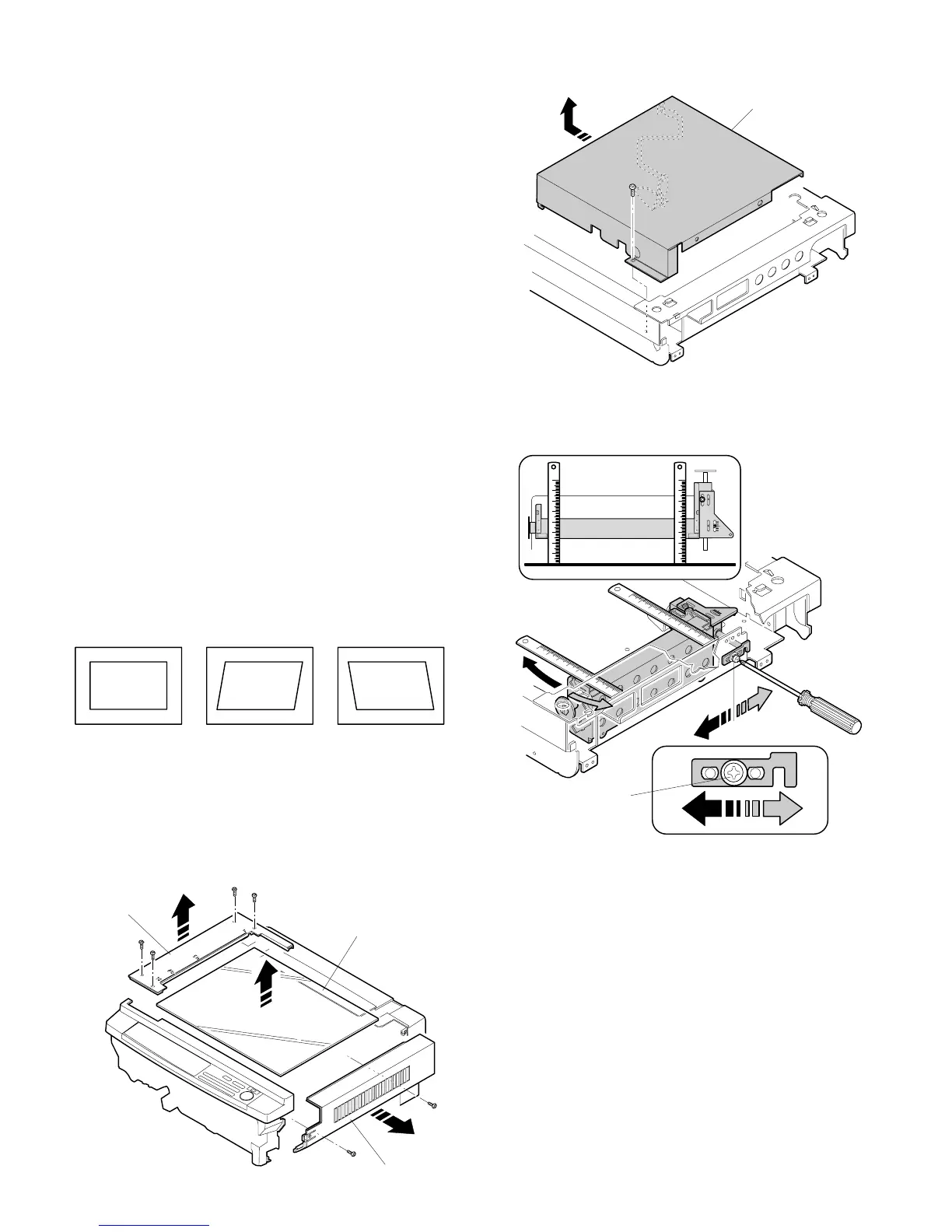
1) Remove the right upper side cabinet and the document refer-
ence plate.
2) Remove the document glass.
3) Loosen the fixing screw of the No. 4/5 mirror unit slide shaft
fixing plate.
4) Move the No. 4/5 mirror unit slide shaft fixing plate in direc-
tions A and B so that the No. 4/5 mirror unit side is in parallel
with the optical unit frame side plate, and fix it.
Use a scale to check the parallelism.
Document Copy A Copy B
Document
reference plate
Document table glass
Right upper side cabinet
Optical unit cover
B
A
A
B
No. 4/5 mirror unit
slide shaft fixing
screw
7 – 7