EN.
5
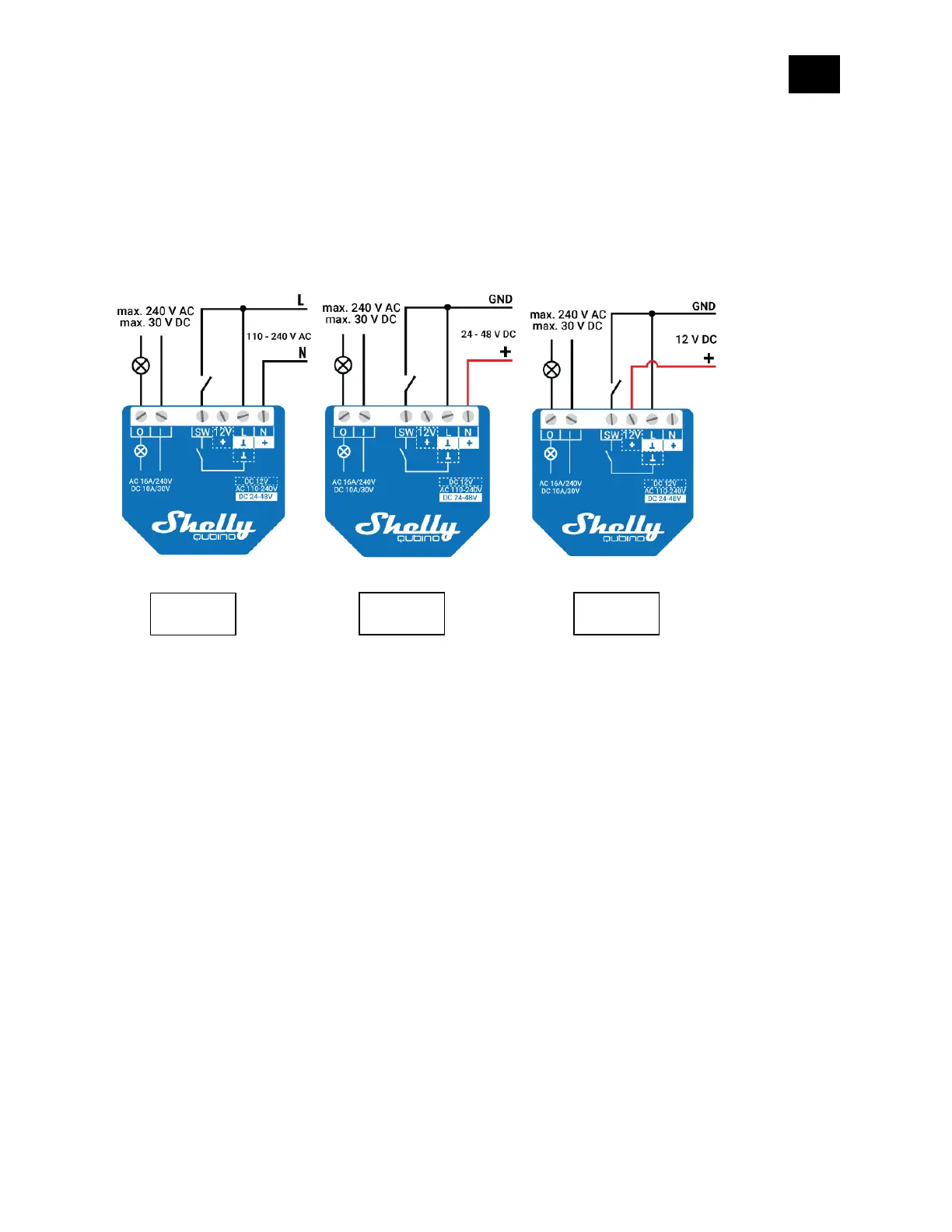
4. Electrical diagrams (110-240 V AC / 24-48 V DC / 12 V
DC)
Connecting to the power grid with power supply 110-240 V AC (Fig. 1), or 24-48 V DC (Fig. 2), or
12 V DC (Fig. 3).
LEGEND
Device terminals:
• N: Neutral terminal
• L: Live terminal (110-240 V AC)
• SW (SW1): Input terminal for switch/push-button controlling O (O1)
• I: Load circuit input terminal
• O (O1): Output terminal for Load circuit (1)
• 12V+: 12 V DC positive terminal
• +: 24 - 48 V DC positive terminal
• ꓕ: 12 / 24 - 48 V DC ground terminal
Wires:
• N: Neutral wire
• L: Live wire (110-240 V AC)
• +: 24 - 48 V DC positive wire
• GND: 12 / 24 - 48 V DC ground wire