1 - SPECIFICATION & STRUCTURE
21
(3) Lowering position
Lowering Position
15
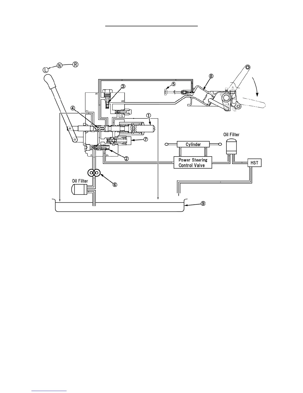
1. Control Valve Spool
2. Flow Priority Valve
3. Lift Check Valve
4. Check Valve
5. Drop Rate Control Valve
6. Hydraulic Pump
7. Relief Valve
8. Hydraulic Cylinder
9. Sump
10. Safety Valve
OIL FLOW - LOWERING POSITION
When the control lever is moved to the "lowering"
position, the control valve spool, 1, is moved forward.
Pressurized supply oil is separated and diverted as in the
"neutral" position.
Oil flow from the hydraulic cylinder, 8, restricted by the
drop rate control valve, 5, enters the valve body at port
'A1' and is directed around the spool, 1, to return to the
reservoir via the 'T2' port. This controlled return allows
the lift arms to fall to the preset position established by
the cutting height lever.
 Loading...