38
Parameter Description
Parameter Description
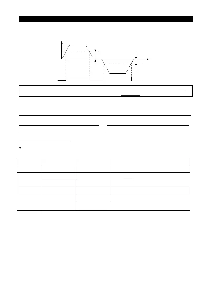
• If P.42=30 and P.43=9999 (the default value), then a signal (FU) is output when the forward or
reverse rotation output frequency exceeds 30Hz.
Note: In this section, FU is the function names of the multi-function output terminals. Please refer to P.40 for
function selection and features. About wiring, please refer to Section 3.5.6
.
5.23 AM Terminal (P.54~P.56, P.190, P.191)
P.54 “AM terminal function selection” P.55 “Frequency monitoring reference”
P.56 “Current monitoring reference”
P.190 “AM output bias”
P.191 “AM output gain”
Between terminal AM and terminal 5, an electric meter can be connected to indicate the
outputcurrent value or the output frequency.
Parameter Factory Setting Setting Range Remarks
--- 4~0 0 45
nehW zH05 P.189=1
55
60Hz
0~650Hz
When P.189=0
--- A005~0 tnerruc detaR 65
190 0 0~8192
191 625 0~8192
Parameters P.190 and P.191 are the
calibrating values. Therefore the default
value for each machine may differ slightly.
<Setting>
• When P.54=0, a voltage of 10V is output at terminal AM if the output frequency of the inverter is
the set value of P.55.
• When P.54=1, a voltage of 10V is output at terminal AM if the output current of the inverter is the
set value of P.56.
• When P.54=2, the output corresponds to the busbar voltage value.If the voltage between +/P and -N
reaches the OV alarm level, the terminal AM will output a voltage of 10V.
• When P.54=3, the output corresponds to the accumulation rate of temperature increase of the
inverter. If the temperature of the IGBT module of the inverter is too high and reaches the NTC
level, a voltage of 10V will be sent out at terminal AM.
FU
Output
frequency
(Hz)
Output signal
OFF OFFON
Time (s)
P.42
P.43
ON OFF
Run forward
Run reverse
 Loading...
