To Next Page
J
Jo BrownSep 9, 2025
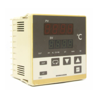
What to do if my Shimaden Controller is in trouble?
- BBobby CochranSep 9, 2025
Examine, repair or replace the product.

What to do if my Shimaden Controller is in trouble?
Examine, repair or replace the product.
Why does the displayed PV value seem incorrect on my Shimaden Controller?
If the displayed PV value seems incorrect on your Shimaden Controller, there are a couple of potential reasons: * The set measuring range code might differ from that of the input sensor or signal. To resolve this, check and ensure that the set measuring range code is correct for the input signal. * There may be erroneous wiring to the input terminals of the sensor. In this case, correct the wiring to the input terminals.
What to do if a key is unable to be operated on Shimaden Controller?
If you find that a key on your Shimaden Controller is not working, consider these possibilities: 1. The keylock function may be enabled. Try releasing the keylock. 2. The product might be deteriorating. In this case, examine the controller and repair or replace it if necessary. 3. If the communication function is active, the controller might be in communication mode (Com). Change the communication setting to the local mode (Loc).
Why does the display go out on my Shimaden Controller and it does not operate?
If the display on the front panel of your Shimaden Controller goes out and the instrument stops operating, here are a few things to check: * There may be a problem with the power supply or wiring connection. Inspect all power-related components and wiring, and ensure everything is correctly connected. * The product itself might be deteriorating. In this case, examine the controller and consider repairing or replacing it.
How to fix too fast ON-OFF action of control output on Shimaden Controller?
If the ON-OFF action of the control output on your Shimaden Controller is too fast: * It's possible that ON-OFF is set for the proportional (P) element of PID control. Change the OFF setting for P to a two-position type ON-OFF action. * The hysteresis value for the ON-OFF action might be too small. Try increasing the hysteresis value.
Covers WARNING, CAUTION, and NOTE for safe operation, grounding, fuses, and handling.
Safety warnings, terminal layout, wiring process, and CT connection for instrument wiring.
Illustrates terminal connections for SR91, SR92, and SR93/SR94 models.
Essential checks and settings required before operating the instrument for the first time.
Supplementary details on manual output and procedures for executing, stopping, and conditions for auto tuning (AT).
Detailed settings for output 1 and 2, including proportional band, hysteresis, integral/derivative times, and limiters.
Configuration for event types, hysteresis, standby actions, and heater break/loop alarm settings.
Explanation of PID (Proportional, Integral, Derivative) parameters and the function of lower/higher limit output limiters.
Lists common issues, their causes, and remedies, including general problems and specific error codes.
 General
| Control Method | PID |
|---|---|
| Input Type | Thermocouple, RTD, DC Voltage, DC Current |
| Output Type | Relay, Voltage Pulse, Current, SSR drive |
| Display | LED Display |
| Power Supply | 100-240V AC |
| Accuracy | ±0.3% of full scale ±1 digit |