26
8-6. Proportional Cycle Time
It should be within a range from 1 to 120 seconds in the case of contact output or SSR drive voltage output.
Proportional cycle time is ON time + OFF time.
The following diagram shows the correlation between proportional cycle time and control output.
ۑ
1
In case the output is 20 %.
Output is ON during 20 % time of the proportional cycle
time, and OFF during 80 % time of proportional cycle
time.
ۑ
2
In case the output is 60 %.
Output is ON during 60 % time of the proportional cycle
time, and OFF during 40 % time of proportional cycle
time.
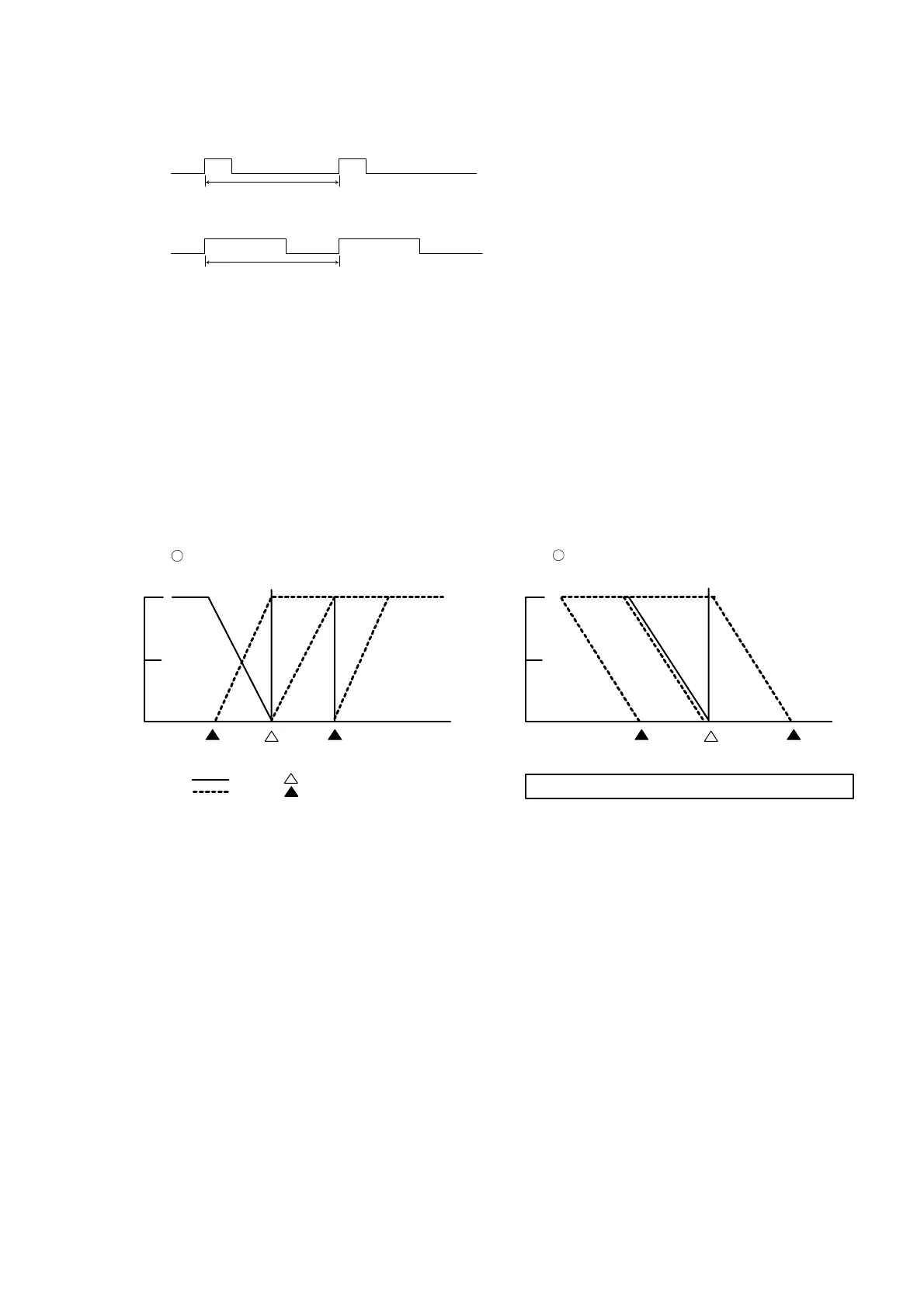
8-7. Control Output Characteristics
(1) One-output
For heating action, set RA (reverse action). For cooling action, set DA (direct action).
(2) Two-output
ۑ
1
In case heating action is OUT1 and cooling action OUT2, set it at RA (reverse action).
ۑ
2
In case heating action is OUT1 and heating action OUT2, set it at DA (direct action).
Control output characteristics with two outputs are shown in the following diagrams.
ۑ
1
shows heating and cooling
control and
ۑ
2
two-stage heating control.
8-8. External input (DI)
The DI signal is detected by the level.
The ON-OFF detection is determined by a 150 msec continuum state across the DI terminal.
The DI type can be specified on the 1-35 DI mode setting screen.
(1) Set value bias (SB)
This can be set by specifying SB (Set value Bias) to DI mode.
SB value can be set on the 0-7 set value bias setting screen.
When DI input signal is OFF : Execution SV = SV
When DI input signal is ON : Execution SV = SV + SB
Note that in case the execution SV lies outside the range of SV limiters, the actual executed SV is restricted by the SV
limiter lower/higher limit values (which can be set on the 1-47 SV limiter lower limit value setting screen or 1-48 SV
limiter higher limit value setting screen).
When auto tuning is executed, the SB signal level is maintained at the level just before the auto tuning was started,
and SB signal detection is not performed.
Proportional Cycle Time
Output ON
Output OFF
Proportional Cycle Time
Output ON
Output OFF
NOTE: In these diagrams, the manual reset (MR) value is -50%.
Output characteristic diagram of 2-output
heating and cooling action
Output characteristic diagram of 2-outpu
heating and heating action
100%
50%
0%
100%
50%
0%
1
2
Control output 1 Control output 1Control output 2 Control output 2
Control output 1:
Control output 2:
DB DB=0
+DB
DB DB=0
+DB
: Target set value (SV)
: DB (dead band)
 Loading...