7
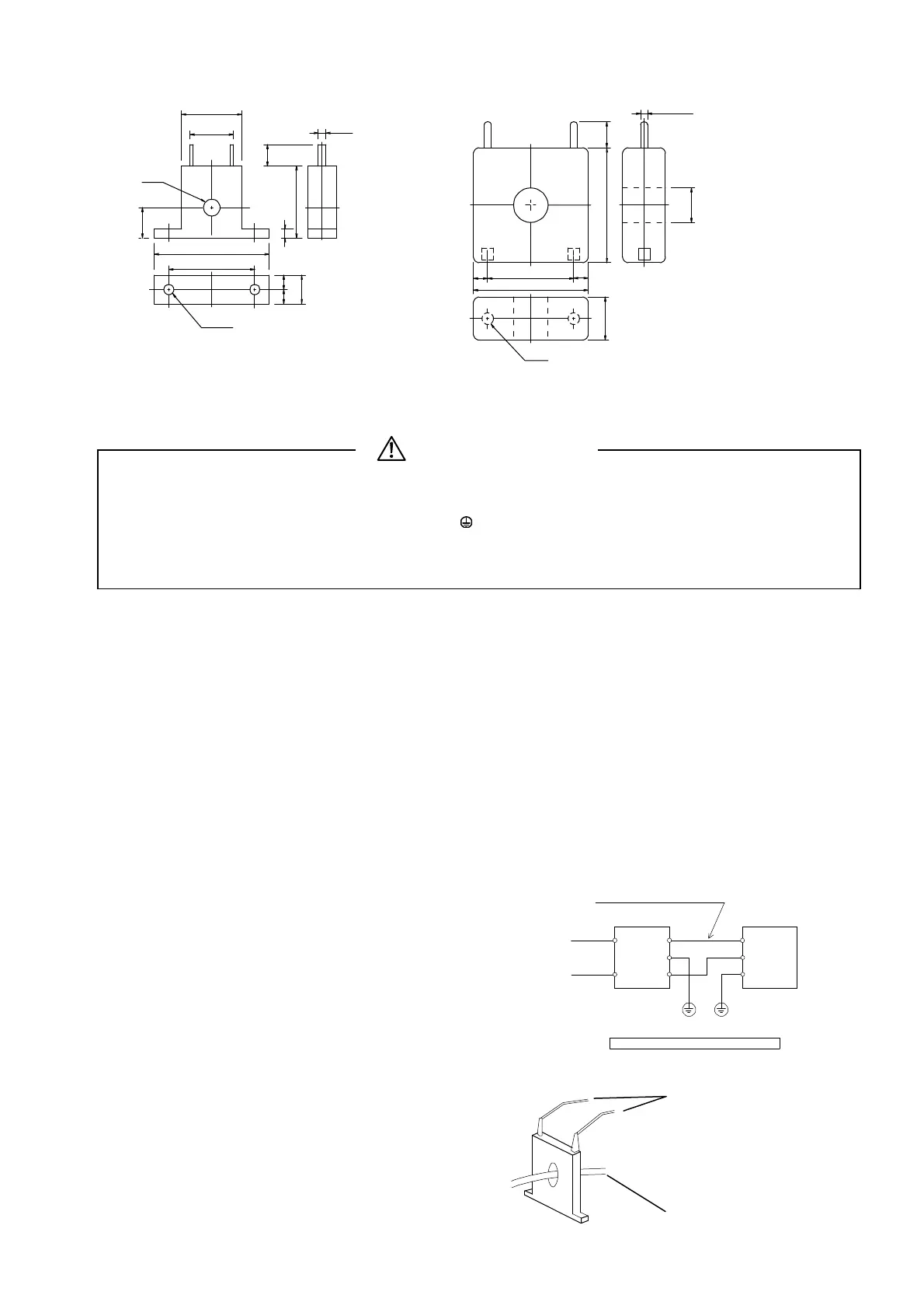
External dimensions of current detectors (CT) of heater break alarm
For 0 to 30 A (CTL-6-S) For 0 to 50 A (CTL-12-S36-8)
3-4. Wiring
WARNING
z Make sure to disconnect this product from any power source during the wiring operation to prevent an electric
shock.
z Be certain that the protective conductor terminal (
) is properly grounded. Otherwise, an electric shock may
result.
z Do not touch wired terminals and other charged elements while they are being energized in order to prevent an
electric shock.
Please pay attention to the following;
ۑ
1
In the wiring operation, follow the terminal layout shown in Section 3-5 and the terminal arrangement in Section 3-
6 and make sure to carry out the correct wiring process.
ۑ
2
Use ring tongue terminals that fit an M3.5 screw and have a width of 7 mm or less.
ۑ
3
In the case of thermocouple input, use a compensating lead wire compatible with the selected type of
thermocouple.
ۑ
4
In the case of R.T.D. input, the resistance of a single lead wire must be 5 or less and the three wires must have
the same resistance.
ۑ
5
The input signal wire must not be accommodated with a high-voltage power cable in the same conduit or duct.
ۑ
6
Shield wiring (single point grounding) is effective against static induction noise.
ۑ
7
Twisting the input wires at short and equal intervals is effective against electromagnetic induction noise.
ۑ
8
In wiring for power supply, use a wire or cable whose performance is equal to or higher than the 600V vinyl
insulated wire having a sectional area of 1 mm
2
or larger.
ۑ
9
The wire for grounding must have a sectional area of 2 mm
2
or larger and must be grounded at a grounding
resistance of 100 or less.
ۑ
10
Clamp the screws of terminals firmly. Clamping torque: 1.0 N • m (10 kgf • cm)
ۑ
11
If the instrument appears to be easily affected by power supply
noise, use a noise filter to prevent malfunctioning. Mount the
noise filter on the grounded panel and make the wire connection
between the noise filter output and the power line terminals of the
controller as short as possible.
ۑ
12
Connection of current detector (CT)
Insert a heater (load) wiring through the hole of the noise
filter meant for the CT.
For the heater (load) wiring, be sure to use wire whose
size matches the heater (load) current.
With this wire, connect the secondary side terminal of CT
to the CT input terminal of the SR90 series controller.
For wiring to the CT input terminal of the controller, use
AWG24-AWG18.
To the CT input terminal of controller
(No polarity)
Heater (load) wiring
Noise filte
Controlle
100-240V AC
50/60Hz
100-240V AC
Make this wire as short as possible.
Recommended noise filter: TDK's RSEL-2003W
IN OUT
Protective
grounding
Protective
grounding
ø 5.8
2- ø 3.5
5.01
21
52
3
01
5 5
30
40
5.7
15
2.8
Unit: mm
ø 2.36
ø21
2-M3
04
40
305
5
51
9
 Loading...


