3.4.2 Create a Cutting Plane
The plane can be rotated, zoom or move.
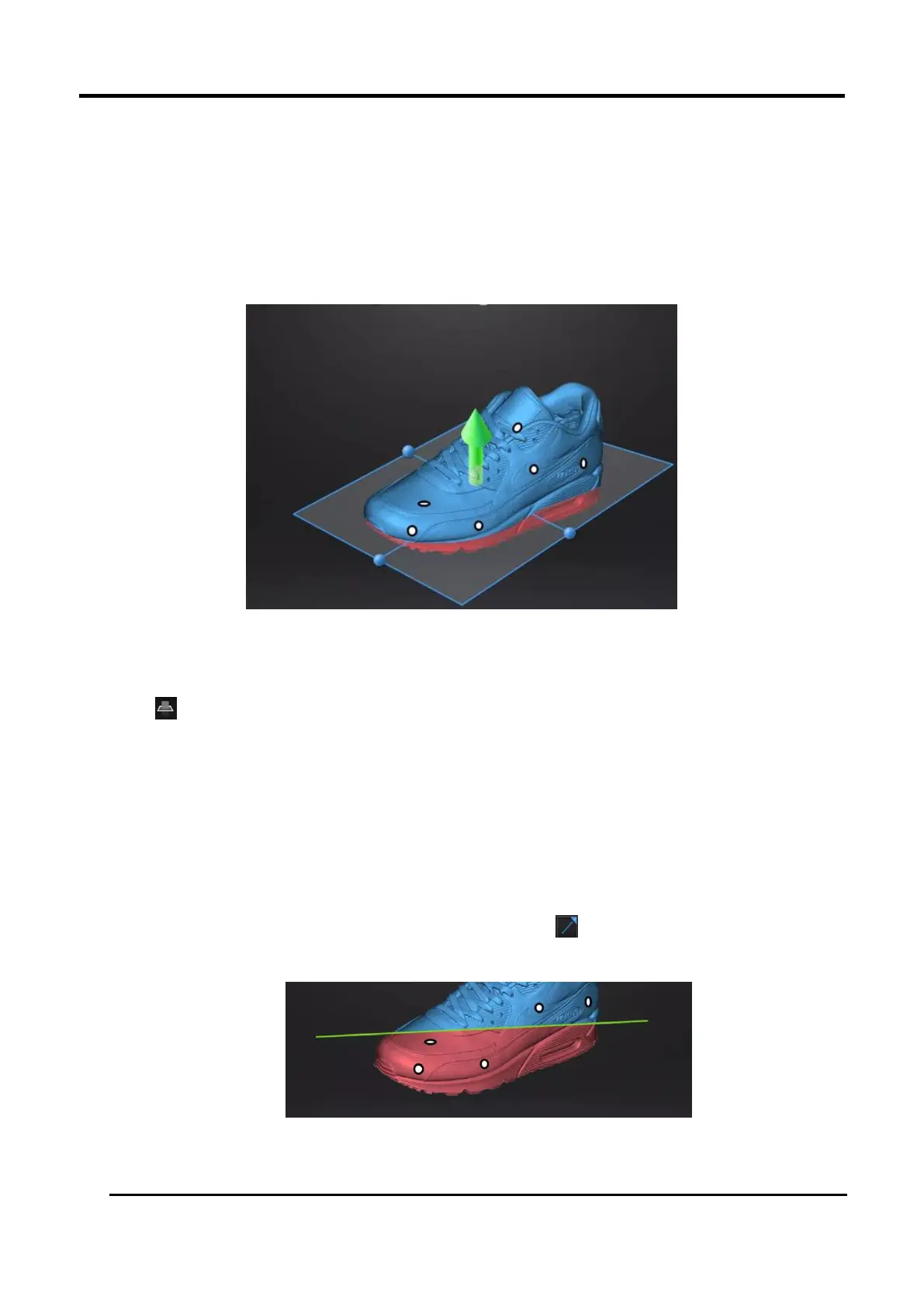
Taking the model below as a reference, after setting the cutting plane, the cutting plane above the
direction of the arrow is valid (displayed in blue). The user can choose whether to save the data in
the reverse direction (displayed in red) or delete it. Although the data in the reverse direction of the
arrow can also be saved, the newly scanned data cannot be added to it.
Figure 3-30 Example
Steps
1.
Click to enter cutting-plane interface.
2.
Choose a create method
Create a cutting plane by fitting point cloud
Press down Shift and Left mouse button to select point cloud data, those selected data is to
form a cutting plane.
Create cutting plane by straight line
Press down Shift and Left mouse button and then click to draw a straight line on the
scanned object, a cutting plane generates from the line is created manually at the same time.
Figure 3-31 Straight Line Cutting Plane





 To Next Page