8
Fig.1: Install the upper 1 1/8” cartridge bearing
D
on the steerer tube of the fork and settle the bearing into the
top of the head tube.
Fig.1: Install the bearing compression ring
E
over the bearing.
Fig.1: Install the top cap
F
over the compression ring.
Fig.1: Install 2 x 25mm head tube spacers
G
onto the steerer tube.
Fig.1: Install the stem
H
that will be used to build the bike onto the steerer tube. This is important to make sure
the steerer tube is cut to the correct length.
WARNING! Do not twist the stem onto the carbon steerer tube. This can result in damage to the
fork.
Mark the steerer tube directly above the stem, then remove the fork from the steerer tube. Make a 2nd mark
2mm below the original mark.
Place a steerer tube cutting guide tool on the steerer tube, with the guide slot aligned with the 2nd mark. Double-
check the measurement, so that the mark is 2mm below the top of the stem with 2x25mm spacers installed
below the stem.
Cut the steerer tube (using a carbon cutting blade, or a blade with a minimum 36 teeth) at the cut mark, remove
the tool, then remove any burrs from the top of the steerer using a fine grit sandpaper.
Repeat steps 1 through 7.
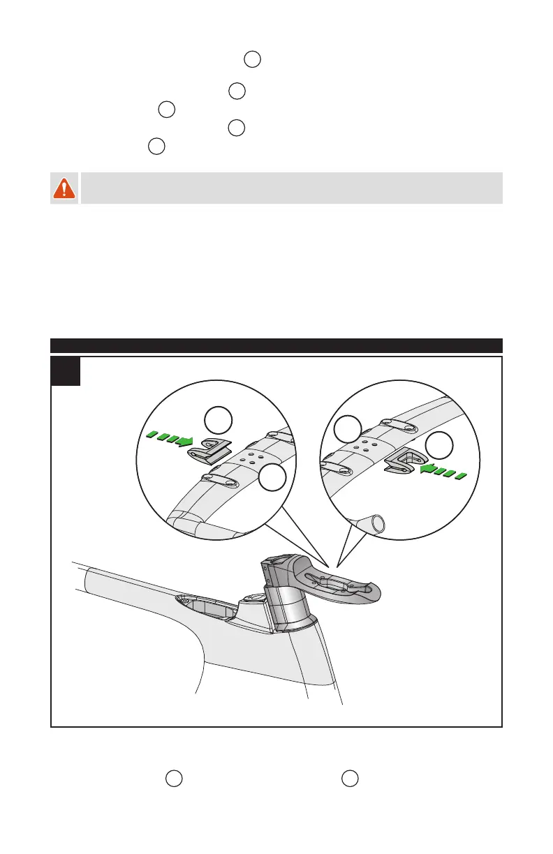
2. INSTALLING THE CARBON AERO HANDLEBAR ON THE AERO STEM
90mm
60mm
J
J
I
I
2
SPECIALIZED AERO STEM:
Fig.2: Determine the desired stem length of 60 or 90mm (longer 80 / 110mm stem available separately) and install
the carbon aero handlebar
I
along with the handlebar position wedge
J
.